
Page 133 - Vibrational Spectroscopic Imaging for Biomedical Applications
P. 133
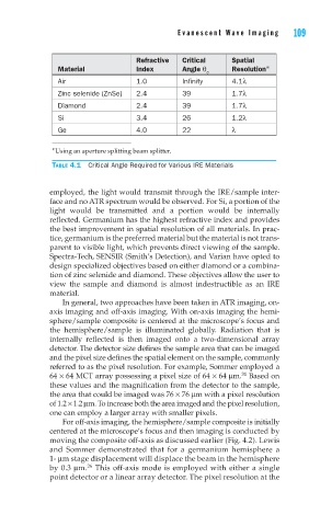
Evanescent W ave Imaging   109


                              Refractive  Critical    Spatial
          Material            Index       Angle θ     Resolution ∗
                                                c
          Air                 1.0         Infinity    4.1λ
          Zinc selenide (ZnSe)  2.4       39          1.7λ
          Diamond             2.4         39          1.7λ
          Si                  3.4         26          1.2λ
          Ge                  4.0         22          λ

         ∗ Using an aperture splitting beam splitter.

         TABLE 4.1  Critical Angle Required for Various IRE Materials


        employed, the light would transmit through the IRE/sample inter-
        face and no ATR spectrum would be observed. For Si, a portion of the
        light would be transmitted and a portion would be internally
        reflected. Germanium has the highest refractive index and provides
        the best improvement in spatial resolution of all materials. In prac-
        tice, germanium is the preferred material but the material is not trans-
        parent to visible light, which prevents direct viewing of the sample.
        Spectra-Tech, SENSIR (Smith’s Detection), and Varian have opted to
        design specialized objectives based on either diamond or a combina-
        tion of zinc selenide and diamond. These objectives allow the user to
        view the sample and diamond is almost indestructible as an IRE
        material.
            In general, two approaches have been taken in ATR imaging, on-
        axis imaging and off-axis imaging. With on-axis imaging the hemi-
        sphere/sample composite is centered at the microscope’s focus and
        the hemisphere/sample is illuminated globally. Radiation that is
        internally reflected is then imaged onto a two-dimensional array
        detector. The detector size defines the sample area that can be imaged
        and the pixel size defines the spatial element on the sample, commonly
        referred to as the pixel resolution. For example, Sommer employed a
                                                        31
        64 × 64 MCT array possessing a pixel size of 64 × 64 μm.  Based on
        these values and the magnification from the detector to the sample,
        the area that could be imaged was 76 × 76 μm with a pixel resolution
        of 1.2 × 1.2 μm. To increase both the area imaged and the pixel resolution,
        one can employ a larger array with smaller pixels.
            For off-axis imaging, the hemisphere/sample composite is initially
        centered at the microscope’s focus and then imaging is conducted by
        moving the composite off-axis as discussed earlier (Fig. 4.2). Lewis
        and Sommer demonstrated that for a germanium hemisphere a
        1- μm stage displacement will displace the beam in the hemisphere
                  26
        by 0.3 μm.  This off-axis mode is employed with either a single
        point detector or a linear array detector. The pixel resolution at the