
Page 55 - Vibrational Spectroscopic Imaging for Biomedical Applications
P. 55
32 Cha pte r T w o
growth in the community of IR synchrotron microspectroscopy users.
The present chapter outlines the latest developments to move this
technology to a new regime, to be able to monitor samples at high
spatial resolution, quickly and in vivo, to allow time-resolved studies
of living biological specimen.
2.2.1 Beamline Design and Implementation
22
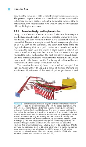
In Fig. 2.1 a schematic of IRENI is shown. The beamline accepts a
swath of radiation from the synchrotron, splits the beam into 12 sepa-
rate beams, and then recombines them into a collimated bundle of
beams that illuminate a sample area at the microscope sample plane
2
of 40 × 60 μm . In the schematic, the individual beam paths are
depicted, showing that each path consists of a toroidal mirror for
refocusing the beam from the source, a plane mirror to redirect the
beam, a window to separate the vacuum from the electron storage
ring and the rest of the beamline. The final two mirrors in each beam-
line are a paraboloidal mirror to collimate the beam and a final plane
mirror to steer the beams into the 3 × 4 array of collimated beams.
Further details of the design are found in Ref. 22.
The beamline has recently been constructed and accepted first
24
light in August 2008. In Fig. 2.2, a series of pictures showing the
synchrotron illumination of the toroidal, plane, paraboloidal and
M4
BM
M3
W
M1
M2
FIGURE 2.1 Schematic (not to scale) diagram of the new IRENI beamline at
the SRC. To keep the system compact and limit the optical aberrations, the
fi rst optical components are 12 identical toroidal mirrors (M1) working in
unity magnifi cation. Each toroid is located 2 m from its source and together
they collect the available horizontal fan of radiation. A water-cooled tube (not
shown), located upstream from the mirrors, blocks the high-energy radiation
emitted by the storage ring, eliminating the need for mirror cooling. The
toroids defl ect the beams, mostly downward, by 85° toward a set of 12 fl at
mirrors (M2). The fl ats direct the beams upward where they leave the UHV
chamber through 12 ZnSe windows (W). The beam foci are above the
windows. The remaining assembly, including a set of 12 paraboloids (M3) to
collimate the beam and a set of 12 plane mirrors (M4) to bundle the beams
along a common axis, are all outside the UHV chamber and will be in a
nitrogen-purged environment. For clarity, only 4 out of the 12 M4 mirrors are
included. (Printed with permission from Ref. 22.)