
Page 623 - Materials Chemistry, Second Edition
P. 623
CAT3525_C20.qxd 1/27/2005 12:54 PM Page 594
594 Waste Management Practices: Municipal, Hazardous, and Industrial
20.6.2 THE MULTIPLE-CHAMBER INCINERATOR
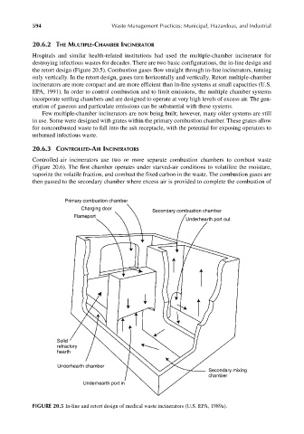
Hospitals and similar health-related institutions had used the multiple-chamber incinerator for
destroying infectious wastes for decades. There are two basic configurations, the in-line design and
the retort design (Figure 20.5). Combustion gases flow straight through in-line incinerators, turning
only vertically. In the retort design, gases turn horizontally and vertically. Retort multiple-chamber
incinerators are more compact and are more efficient than in-line systems at small capacities (U.S.
EPA, 1991). In order to control combustion and to limit emissions, the multiple chamber systems
incorporate settling chambers and are designed to operate at very high levels of excess air. The gen-
eration of gaseous and particulate emissions can be substantial with these systems.
Few multiple-chamber incinerators are now being built; however, many older systems are still
in use. Some were designed with grates within the primary combustion chamber. These grates allow
for noncombusted waste to fall into the ash receptacle, with the potential for exposing operators to
unburned infectious waste.
20.6.3 CONTROLLED-AIR INCINERATORS
Controlled-air incinerators use two or more separate combustion chambers to combust waste
(Figure 20.6). The first chamber operates under starved-air conditions to volatilize the moisture,
vaporize the volatile fraction, and combust the fixed carbon in the waste. The combustion gases are
then passed to the secondary chamber where excess air is provided to complete the combustion of
Primary combustion chamber
Charging door
Secondary combustion chamber
Flameport
Underhearth port out
Solid
refractory
hearth
Underhearth chamber
Secondary mixing
chamber
Underhearth port in
FIGURE 20.5 In-line and retort design of medical waste incinerators (U.S. EPA, 1989a).