
Page 164 - Welding Robots Technology, System Issues, and Applications
P. 164
152 Welding Robots
functionalities of the equipment used: one ABB IRB1400 S4CPlus industrial robot,
a SIEMENS VS710 CCD camera and a ServoRobot M-Spot Laser 3D camera. The
welding power source (MIG/MAG power source ESAB A350) is controlled from
the robot controller using the welding sequence presented in Figure 5.2, and a
client-server programming strategy (see Section 4.5.1).
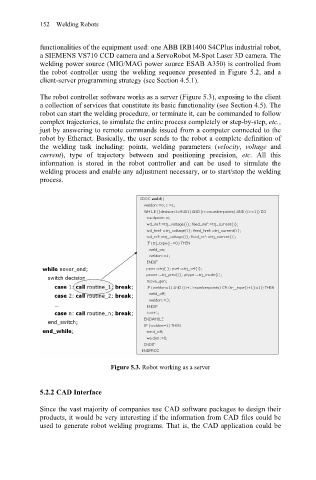
The robot controller software works as a server (Figure 5.3), exposing to the client
a collection of services that constitute its basic functionality (see Section 4.5). The
robot can start the welding procedure, or terminate it, can be commanded to follow
complex trajectories, to simulate the entire process completely or step-by-step, etc.,
just by answering to remote commands issued from a computer connected to the
robot by Ethernet. Basically, the user sends to the robot a complete definition of
the welding task including: points, welding parameters (velocity, voltage and
current), type of trajectory between and positioning precision, etc. All this
information is stored in the robot controller and can be used to simulate the
welding process and enable any adjustment necessary, or to start/stop the welding
process.
Figure 5.3. Robot working as a server
5.2.2 CAD Interface
Since the vast majority of companies use CAD software packages to design their
products, it would be very interesting if the information from CAD files could be
used to generate robot welding programs. That is, the CAD application could be