
Page 169 - Welding Robots Technology, System Issues, and Applications
P. 169
Robotic Welding: Application Examples 157
ASCII file, it is very easy to extract the above-mentioned information, using a
simple application (Figure 5.5) that identifies each added welding layer, the
trajectories and the related welding parameters, and stores that information in a
known way. The definition used here is represented in Figure 5.6.
The generated “.wdf” file is used as input for the application represented in Figure
5.7. This application shows the available definition with the help of several push-
down software buttons, and enables the user to change welding parameters, correct
points and orientations, simulate the whole process using the real robot and the real
piece to weld. The simulation is very realistic, making the final program ready for
production. A complete collection of tools was designed to help the user to adjust
the points, add extra points, add approach and fly away trajectories, adjust welding
parameters, test and simulate the whole process until the operation is as desired.
The functions included in these application tools use exclusively the ActiveX
control PCROBNET2003 [8], developed by the first author to interface with the
RPC services available from the robot controller (see Section 4.5.1).
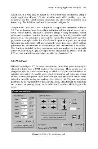
5.2.3 WeldPanel
With this tool (Figure 5.7) the user can manipulate the welding points that may be
obtained initially from a CAD model of the work-piece. Those points may be
changed or adjusted, and extra ones may be added as a way to avoid collisions, to
optimize trajectories, etc., and to achieve best performance. All points are always
referred to the welding torch Tool Center Point (TCP) and to a Work-Object frame
defined in the table holding the working object (Figure 5.4). The user may adjust
points just by moving the robot to the desired position, a task that can be done from
the computer or passing control to the robot teach pendant, which is generally
easier.
Figure 5.8. Shell of the WeldAdjust tool