
Page 165 - Welding Robots Technology, System Issues, and Applications
P. 165
the environment used for specifying the way the welding robots should execute the
welding operation on the specified parts. Robotic Welding: Application Examples 153
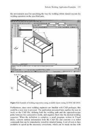
Work-object
Figure 5.4. Example of welding trajectories using available layers (using AUTOCAD 2004)
Furthermore, since most welding engineers are familiar with CAD packages, this
could be a nice way to proceed. The application presented here enables the user to
work on the CAD file, defining both the welding path and the approach/escape
paths between two consecutive welds, and organize them into the desired welding
sequence. When the definition is complete, a small program, written in Visual
Basic, extracts motion information from the CAD file and converts it to robot
commands that can be immediately tested for detailed tuning. A set of tools is then
available to speed up the necessary corrections, which can be made on-line with