
Page 166 - Welding Robots Technology, System Issues, and Applications
P. 166
154 Welding Robots
the robot moving. After a few simulations (with the robot performing all the
programmed motions without welding) the program is ready for production. The
whole process can be completed in just some minutes to a few hours, depending on
the size and complexity of the component to be welded, representing a huge
reduction of programming and setup time. Besides, most of the work is really easy
off-line programming.
Consequently, having the software tools available and meeting a specific request
from industry, a solution was designed using AUTOCAD [7] and DXF files
(currently standard files for all CAD software tools). If the user follows some basic
rules, and produces a DXF file with all the information needed, then the
application developed is capable of extracting that information from the CAD file,
and is able to produce a robot program almost ready for production.
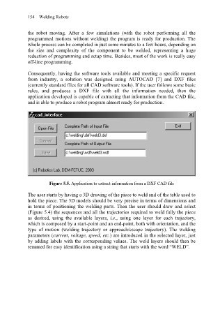
Figure 5.5. Application to extract information from a DXF CAD file
The user starts by having a 3D drawing of the piece to weld and of the table used to
hold the piece. The 3D models should be very precise in terms of dimensions and
in terms of positioning the welding parts. Then the user should draw and select
(Figure 5.4) the sequences and all the trajectories required to weld fully the piece
as desired, using the available layers, i.e., using one layer for each trajectory,
which is composed by a start-point and an end-point, both with orientation, and the
type of motion (welding trajectory or approach/escape trajectory). The welding
parameters (current, voltage, speed, etc.) are introduced in the selected layer, just
by adding labels with the corresponding values. The weld layers should then be
renamed for easy identification using a string that starts with the word “WELD”.