
Page 168 - Welding Robots Technology, System Issues, and Applications
P. 168
156 Welding Robots
The next information is the type of trajectory, to distinguish between welding
trajectories and approach/escape trajectories. After that should be specified the
welding current, and then the welding voltage. Finally, the welding speed is
specified. All these parameters are separated by spaces, constituting a definition
string. Consequently, a label on a welding trajectory is a string that looks like this
one:
WELD 0 150.0 20.0 10 0
which defines a welding trajectory (0 – welding, 1 – approach/escape, Figure 5.6),
with a welding current of 150 A, a welding voltage of 20 V, a welding speed of 10
mm/s and maximum precision in achieving the end-point.
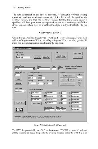
Figure 5.7. Shell of the WeldPanel tool
The DXF file generated by the CAD application (AUTOCAD in our case) includes
all the information added to specify the welding process. Since the DXF file is an