
Page 357 - Fluid Power Engineering
P. 357
Planning and Execution of W ind Projects 317
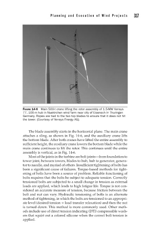
FIGURE 14-6 Main 500-t crane lifting the rotor assembly of 1.5-MW Vensys
77, 100-m hub in Nuekirchen wind farm near city of Eisenach in Thuringen
Germany. Ropes are tied to the two top blades to ensure that it does not hit
the tower. (Courtesy of Vensys Energy AG).
The blade assembly starts in the horizontal plane. The main crane
attaches a sling, as shown in Fig. 14-6, and the auxiliary crane lifts
the bottom blade. After both cranes have lifted the entire assembly to
sufficient height, the auxiliary crane lowers the bottom blade while the
main crane continues to lift the rotor. This continues until the entire
assembly is vertical, as in Fig. 14-6.
Most of the joints in the turbine are bolt joints—from foundation to
tower joint, between towers, blades to hub, hub to generator, genera-
tor to nacelle, and myriad of others. Insufficient tightening of bolts has
been a significant cause of failures. Torque-based methods for tight-
ening of bolts have been a source of problem. Reliable functioning of
bolts requires that the bolts be subject to adequate tension. Correctly
tensioned bolts are subjected to a small change in tension as external
loads are applied, which leads to high fatigue life. Torque is not con-
sidered an accurate measure of tension, because friction between the
bolt and nut can vary. Hydraulic tensioning of bolts is an alternate
method of tightening, in which the bolts are tensioned to an appropri-
ate level (desired tension + load transfer relaxation) and then the nut
is turned down. This method is more commonly used. Other meth-
ods include use of direct tension indicating (DTI) compressible wash-
ers that squirt out a colored silicone when the correct bolt tension is
applied.