
Page 141 - Wire Bonding in Microelectronics
P. 141
W ir e Bond Testing 119
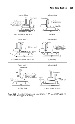
Initial conditions Failure mode 1
Wire Shearing ram Shearing ram
Bond shoulder Ball separated
at bonding pad
Interfacial contact
ball bond weld area
Bonding pad Ball bond ∆h Bonding
pad intact
Test specimen
Specimen Clamp
(a) Normal test configuration (b) Ball lift
Failure mode 2 Failure mode 3
Shearing ram Shearing ram
Bonding pad lifts
Gold left on pad taking portion of
underlying substrate
material with it
Bonding
pad
(c) Ball shear — leaving gold on pad (d) Cratering
Failure mode 4 Failure mode 5
Shearing ram
Wire
Shearing ram
Ball sheared too high
(off line, etc.) only a
portion of shoulder
and ball top removed Tipped
Bonding substrate Ram
pad contacts pad
or substrate
(e) Wire shear (f) Ram contacts substrate
FIGURE 4A-1 Shear test failure modes. (After Charles [4-47] and ASTM F 1269-06,
with modifi cations.) (© ASTM 2006)