
Page 36 - Wire Bonding in Microelectronics
P. 36
Ultrasonic Bonding Systems and Technologies 15
A B
D
C
E
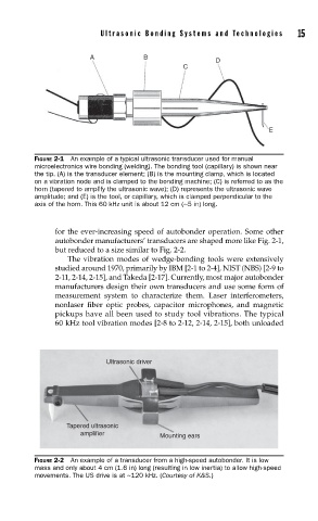
FIGURE 2-1 An example of a typical ultrasonic transducer used for manual
microelectronics wire bonding (welding). The bonding tool (capillary) is shown near
the tip. (A) is the transducer element; (B) is the mounting clamp, which is located
on a vibration node and is clamped to the bonding machine; (C) is referred to as the
horn (tapered to amplify the ultrasonic wave); (D) represents the ultrasonic wave
amplitude; and (E) is the tool, or capillary, which is clamped perpendicular to the
axis of the horn. This 60 kHz unit is about 12 cm (~5 in) long.
for the ever-increasing speed of autobonder operation. Some other
autobonder manufacturers’ transducers are shaped more like Fig. 2-1,
but reduced to a size similar to Fig. 2-2.
The vibration modes of wedge-bonding tools were extensively
studied around 1970, primarily by IBM [2-1 to 2-4], NIST (NBS) [2-9 to
2-11, 2-14, 2-15], and Takeda [2-17]. Currently, most major autobonder
manufacturers design their own transducers and use some form of
measurement system to characterize them. Laser interferometers,
nonlaser fiber optic probes, capacitor microphones, and magnetic
pickups have all been used to study tool vibrations. The typical
60 kHz tool vibration modes [2-8 to 2-12, 2-14, 2-15], both unloaded
Ultrasonic driver
Tapered ultrasonic
amplifier
Mounting ears
FIGURE 2-2 An example of a transducer from a high-speed autobonder. It is low
mass and only about 4 cm (1.6 in) long (resulting in low inertia) to allow high-speed
movements. The US drive is at ~120 kHz. (Courtesy of K&S.)