
Page 38 - Wire Bonding in Microelectronics
P. 38
Ultrasonic Bonding Systems and Technologies 17
0.400
0.320 T
Tool length (in) 0.240
0.160
3 2
0.080
1
0
100 80 60 40 20 0
Vibration amplitude (µ in)
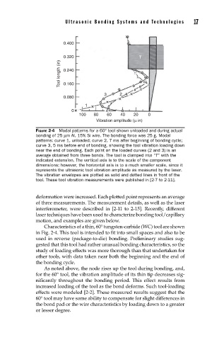
FIGURE 2-4 Modal patterns for a 60° tool shown unloaded and during actual
bonding of 25 µm Al, 15% Si wire. The bonding force was 25 g. Modal
patterns: curve 1, unloaded; curve 2, 7 ms after beginning of bonding cycle;
curve 3, 5 ms before end of bonding, showing the tool vibration loading down
near the end of bonding. Each point on the loaded curves (2 and 3) is an
average obtained from three bonds. The tool is clamped into “T” with the
indicated extension. The vertical axis is to the scale of the component
dimensions; however, the horizontal axis is to a much smaller scale, since it
represents the ultrasonic tool vibration amplitude as measured by the laser.
The vibration envelopes are plotted as solid and dotted lines in front of the
tool. These tool vibration measurements were published in [2-7 to 2-11].
deformation were increased. Each plotted point represents an average
of three measurements. The measurement details, as well as the laser
interferometer, were described in [2-11 to 2-15]. Recently, different
laser techniques have been used to characterize bonding tool/capillary
motion, and examples are given below.
Characteristics of a thin, 60° tungsten-carbide (WC) tool are shown
in Fig. 2-4. This tool is intended to fit into small spaces and also to be
used in reverse (package-to-die) bonding. Preliminary studies sug-
gested that this tool had rather unusual bonding characteristics, so the
study of loading effects was more thorough than that undertaken for
other tools, with data taken near both the beginning and the end of
the bonding cycle.
As noted above, the node rises up the tool during bonding, and,
for the 60° tool, the vibration amplitude of its thin tip decreases sig-
nificantly throughout the bonding period. This effect results from
increased loading of the tool as the bond deforms. Such tool-loading
effects were modeled [2-2]. These measured results suggest that the
60° tool may have some ability to compensate for slight differences in
the bond pad or the wire characteristics by loading down to a greater
or lesser degree.