
Page 39 - Wire Bonding in Microelectronics
P. 39
18 Cha pte r T w o
0.800
0.640 T
Distance from tool tip (in) 0.480 Tungsten carbide tool
0.320
0.160
3 1
0
120 100 80 60 40 20 0
Vibration amplitude (µ in)
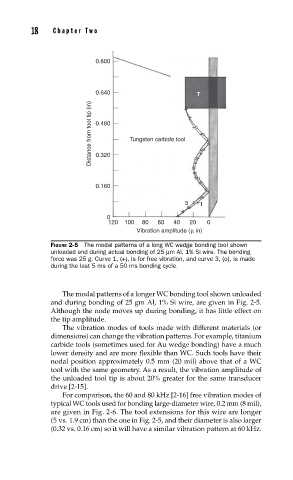
FIGURE 2-5 The modal patterns of a long WC wedge bonding tool shown
unloaded and during actual bonding of 25 µm Al, 1% Si wire. The bonding
force was 25 g. Curve 1, (+), is for free vibration, and curve 3, (o), is made
during the last 5 ms of a 50 ms bonding cycle.
The modal patterns of a longer WC bonding tool shown unloaded
and during bonding of 25 gm Al, 1% Si wire, are given in Fig. 2-5.
Although the node moves up during bonding, it has little effect on
the tip amplitude.
The vibration modes of tools made with different materials (or
dimensions) can change the vibration patterns. For example, titanium
carbide tools (sometimes used for Au wedge bonding) have a much
lower density and are more flexible than WC. Such tools have their
nodal position approximately 0.5 mm (20 mil) above that of a WC
tool with the same geometry. As a result, the vibration amplitude of
the unloaded tool tip is about 20% greater for the same transducer
drive [2-15].
For comparison, the 60 and 80 kHz [2-16] free vibration modes of
typical WC tools used for bonding large-diameter wire, 0.2 mm (8 mil),
are given in Fig. 2-6. The tool extensions for this wire are longer
(5 vs. 1.9 cm) than the one in Fig. 2-5, and their diameter is also larger
(0.32 vs. 0.16 cm) so it will have a similar vibration pattern at 60 kHz.