
Page 388 - Characterization and Properties of Petroleum Fractions - M.R. Riazi
P. 388
P2: IML/FFX
QC: IML/FFX
T1: IML
P1: IML/FFX
AT029-09
AT029-Manual-v7.cls
June 22, 2007
AT029-Manual
14:25
368 CHARACTERIZATION AND PROPERTIES OF PETROLEUM FRACTIONS
Since vapor and liquid leaving a flash unit are in equilib-
T, pressure is reduced to P at which infinitesimal amount
of vapor is produced (∼V = 0 or beginning of vaporization). rium from Eq. (6.201) we have
Through bubble-P calculations this pressure is calculated.
Bubble point pressure for a mixture at temperature T is sim- (9.1) y i = K i x i
ilar to the vapor pressure of a pure substance at given T. (iii) in which K i is the equilibrium ratio of component i at T
In bubble-T calculations, liquid of known composition (x i ) and P and compositions x i and y i . Calculations of K i values
at pressure P is heated until temperature T at which first have been discussed in Section 6.8.2.3. Mole balance equation
molecules of vapor are formed. The corresponding tempera- around a separator unit (Fig. 9.2) for component i is given by
ture is known as bubble point temperature at pressure P and the following equation:
estimation of this temperature is known as bubble-T calcu-
lations. In this type of calculations, P = P F and temperature (9.2) 1 × z i = L F × x i + V F × y i
T at which small amount of vapor is formed can be calcu- Substituting for L F = 1 − V F , replacing for y i from Eq. (9.1),
lated. Bubble point temperature or saturation temperature and solving for x i gives the following:
for a mixture is equivalent to the boiling point of a pure sub-
z i
stance at pressure P. (iv) In dew-P calculations a vapor of (9.3) x i =
known composition (y i = z i ) at temperature T = T F is com- 1 + V F (K i − 1)
pressed to pressure P at which infinitesimal amount of liquid Substituting Eq. (9.3) into Eq. (9.1) gives a relation for cal-
is produced (∼L = 0 or beginning of condensation). Through culation of y i . Since for both vapor and liquid products we
dew-P calculations this pressure known as dew point pressure must have x i = y i = 1or (y i − x i ) = 0. Substituting x i
(P d ) is calculated. For a pure substance the dew point pressure and y i from the above equations gives the following objective
at temperature T is equivalent to its vapor pressure at T. (v) In function for calculation of V F :
dew-T calculations, a vapor of known composition is cooled N
at constant P until temperature T at which first molecules of (9.4) F(V F ) = z i (K i − 1) = 0
liquid are formed. The corresponding temperature is known i=1 1 + V F (K i − 1)
as dew point temperature at pressure P and estimation of this Reservoir engineers usually refer to this equation as
temperature is known as dew-T calculations. In these calcu- Rachford–Rice method [1]. When V F = 0, the fluid is a liq-
lations, P = P F and temperature T at which condensation be- uid at its bubble point (saturated liquid) and if V F = 1, the
gins is calculated. Flash, bubble, and dew points calculations system is a vapor at its dew point (saturated vapor). Correct
are widely used in the petroleum industry and are discussed solution of Eq. (9.4) should give positive values for all x i and
in the following sections.
y i , which match the conditions x i = y i = 1. The follow-
ing step-by-step procedure can be used to calculate V F :
9.2.1 Flash Calculations—Gas-to-Oil Ratio
1. Consider the case that values of z i (feed composition), T,
In typical flash calculations a feed fluid mixture of compo- and P (flash condition) are known.
sition z i enters a separator at T and P. Products of a flash 2. Calculate all K i values assuming ideal solution (i.e., using
separator for F mol of feed are V mol of vapor with composi- Eqs. 6.198, 6.202, or 6.204). In this way knowledge of x i
tion y i and L mol of liquid with composition x i . Calculations and y i are not required.
can be performed for each mole of the feed (F = 1). By calcu- 3. Guess an estimate of V F value. A good initial guess may
lating vapor-to-feed mole ratio (V F = V/F), one can calculate be calculated from the following relationship [2]: V F = A/
the gas-to-oil ratio (GOR) or gas-to-liquid ratio (GLR). This (A − B), where A = [z i (K i − 1)] and B = [z i (K i − 1)/
parameter is particularly important in operation of surface K i ].
separators at the oil production fields in which production of 4. Calculate F(V) from Eq. (9.4) using assumed value of V F in
maximum liquid (oil) is desired by having low value of GOR. Step 3.
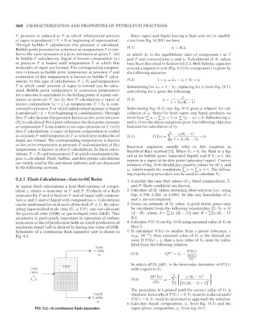
Schematic of a continuous flash separator unit is shown in 5. If calculated F(V F ) is smaller than a preset tolerance, ε
Fig. 9.2. (e.g., 10 −15 ), then assumed value of V F is the desired an-
swer. If F(V F ) >ε, then a new value of V F must be calcu-
lated from the following relation:
Vapor
V moles new F(V F )
y i (9.5) V F = V F − dF(V F )
dV F
In which dF(V F )/dV F is the first-order derivative of F(V F )
T & P
Feed with respect to V F .
1 mole
N
z i dF(V F ) z i (K i − 1) 2
T F , P F (9.6) =−
2
dV F V F (K i − 1) + 1
i=1
The procedure is repeated until the correct value of V F is
Liquid obtained. Generally, if F(V F ) > 0, V F must be reduced and if
L moles F(V F ) < 0, V F must be increased to approach the solution.
x i
6. Calculate liquid composition, x i , from Eq. (9.3) and the
FIG. 9.2—A continuous flash separator. vapor phase composition, y i , from Eq. (9.1).
--`,```,`,``````,`,````,```,,-`-`,,`,,`,`,,`---
Copyright ASTM International
Provided by IHS Markit under license with ASTM Licensee=International Dealers Demo/2222333001, User=Anggiansah, Erick
No reproduction or networking permitted without license from IHS Not for Resale, 08/26/2021 21:56:35 MDT