
Page 389 - Characterization and Properties of Petroleum Fractions - M.R. Riazi
P. 389
P2: IML/FFX
QC: IML/FFX
P1: IML/FFX
T1: IML
14:25
June 22, 2007
AT029-09
AT029-Manual-v7.cls
AT029-Manual
Gas II
Gas III
Gas I 9. APPLICATIONS: PHASE EQUILIBRIUM CALCULATIONS 369
Reservoir Stage II Stage III
Fluid Stage I o o
o
T=37.8 C T=35 C T=32.2 C
P=21.7 P=5.2 P=1.01
o
T=118.3 C bar Liquid I bar Liquid II bar Liquid III
P=164.5 bar (Crude Oil)
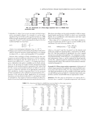
FIG. 9.3—Schematic of a three-stage separator test in a Middle East
production field.
The above procedure can be easily extended to LLE or vapor–
7. Calculate K i values from a more accurate method using x i
and y i calculated in Step 6. For example, K i can be calcu- liquid–liquid equilibrium (VLLE) in which two immiscible
lated from Eq. (6.197) by a cubic equation of state (i.e., SRK liquids are in equilibrium with themselves and their vapor
L
V
EOS) through calculating ˆ φ and ˆ φ using Eq. (6.126). Sub- phase (see Problem 9.1).
i
i
L
V
sequently ˆ f and ˆ f can be calculated from Eq. (6.113). For Once value of V F is calculated in a VLE flash calculation,
i i
isothermal flash we must have the gas-to-liquid ratio (GLR) or gas-to-oil ratio (GOR) can be
2 calculated from the following relation [7]:
N L
ˆ f i
(9.7) − 1 <ε 5
ˆ f V
1.33 × 10 ρ L V F
i=1 i (9.8) GOR scf stb =
(1 − V F )M L
where ε is a convergence tolerance, (e.g., 1 × 10 −13 ). 3
8. Repeat a new round of calculations from Step 4 with calcu- where ρ L (in g/cm ) and M L (in g/mol) are the density and
lated V F from the previous round until there is no change molecular weight of a liquid product, respectively (see Prob-
in values of V F , x i , and y i and inequality (9.7) is satisfied. lem 9.2). The best method of calculation of ρ L for a liquid
mixture is to calculate it through Eq. (7.4), using pure compo-
Various other methods of flash calculations for fast con- nent liquid densities. If the liquid is at atmospheric pressure
vergence are given in different references [1–4]. For example, and temperature, then ρ L can be replaced by liquid specific
Whitson [1] suggests that the initial guess for V F must be gravity, SG L , which may also be calculated from Eq. (7.4) and
between two values of V F,min and V F,max to obtain fast conver- components SG values. The method of calculations is demon-
gence. Michelsen also gives a stability test for flash calcula- strated in Example 9.1.
tions [5, 6]. Accuracy of results of VLE calculations largely
depends on the method used for estimation of K i values and Example 9.1 (Three-stage surface separator)—Schematic of
for this reason recommended methods in Table 6.15 can be a three-stage separator for analysis of a reservoir fluid to pro-
used as a guide for selection of an appropriate method for duce crude oil is shown in Fig. 9.3. The composition of reser-
VLE calculation. Another important factor for the accuracy voir fluid and products as well as GOR in each stage and the
overall GOR are given in Table 9.1. Calculate final crude com-
of VLE calculations is the method of characterization of C 7+
fraction of the petroleum fluid. Application of continuous position and the overall GOR from an appropriate model.
functions, as it was shown in Section 4.5, can improve results
of calculations. The impact of characterization on phase be- Solution—The first step in calculation is to express the C 7+
havior of reservoir fluids is also demonstrated in Section 9.2.3. fraction into a number of pseudocomponents with known
TABLE 9.1—Experimental data for a Middle East reservoir fluid in a three-stage separator
test. Taken with permission from Ref. [7].
1st-Stage 2nd-Stage 3rd-Stage 3rd-Stage
No. Component Feed gas gas gas liquid
1 N 2 0.09 0.77 0.16 0.15 0.00
2 CO 2 2.09 4.02 3.92 1.41 0.00
3 H 2 S 1.89 1.35 4.42 5.29 0.00
4 H 2 O 0.00 0.00 0.00 0.00 0.00
5 C 1 29.18 63.27 31.78 5.10 0.00
6 C 2 13.60 20.15 33.17 26.33 0.19
7 C 3 9.20 7.56 18.84 36.02 1.88
8 n-C 4 4.30 1.5 4.14 13.6 3.92
9 i-C 4 0.95 0.43 1.24 3.62 0.62
10 n-C 5 2.60 0.36 0.92 3.50 4.46
11 i-C 6 1.38 0.24 0.63 2.46 2.11
12 C 6 4.32 0.24 0.57 2.09 8.59
13 C 7+ 30.40 0.11 0.21 0.43 78.23
SG at 60 F 0.8150
◦
Temp, F 245 105 100 90 90
◦
Pressure, psia 2387 315 75 15 15
GOR, scf/stb 850 601 142 107
--`,```,`,``````,`,````,```,,-`-`,,`,,`,`,,`---
Copyright ASTM International
Provided by IHS Markit under license with ASTM Licensee=International Dealers Demo/2222333001, User=Anggiansah, Erick
No reproduction or networking permitted without license from IHS Not for Resale, 08/26/2021 21:56:35 MDT