
Page 481 - Acquisition and Processing of Marine Seismic Data
P. 481
472 10. NORMAL MOVEOUT CORRECTION AND STACKING
limit values, a higher number of traces in early CDP gather. This is known as “mean stack” and
arrivals is involved in the stacking process. is schematically illustrated in the upper right
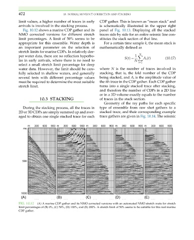
Fig. 10.12 shows a marine CDP gather and its panel of Fig. 10.13. Displaying all the stacked
NMO corrected versions for different stretch traces side by side for an entire seismic line con-
limit percentages. A limit of 50% seems to be stitutes the stack section of that line.
appropriate for this ensemble. Water depth is For a certain time sample k, the mean stack is
an important parameter on the selection of mathematically defined as
stretch limits for marine CDPs. In relatively dee-
N
per water data, there are no reflection hyperbo- 1 X
StðÞ ¼ A i tðÞ (10.17)
las in early arrivals, where there is no need to N
i¼1
select a small stretch limit percentage for deep
water data. However, the limit should be care- where N is the number of traces involved in
fully selected in shallow waters, and generally stacking, that is, the fold number of the CDP
several tests with different percentage values being stacked, and A i is the amplitude value of
must be required to determine the most suitable the ith trace in the CDP gather. Each CDP gather
stretch limit. turns into a single stacked trace after stacking,
and therefore the number of CDPs in a 2D line
or in a 3D volume exactly equals to the number
10.3 STACKING of traces in the stack section.
Geometry of the ray paths for each specific
During the stacking process, all the traces in type of ensemble from raw shot gathers to a
2D or 3D CDPs are simply summed up and aver- stacked trace, and their corresponding example
aged to obtain one single stacked trace for each trace gathers are given in Fig. 10.14. The seismic
FIG. 10.12 (A) A marine CDP gather and its NMO corrected versions with an automated NMO stretch mute for stretch
limit percentages of (B) 0%, (C) 50%, (D) 100%, and (E) 200%. A stretch limit of 50% seems to be suitable for this real marine
CDP gather.