
Page 485 - Acquisition and Processing of Marine Seismic Data
P. 485
476 10. NORMAL MOVEOUT CORRECTION AND STACKING
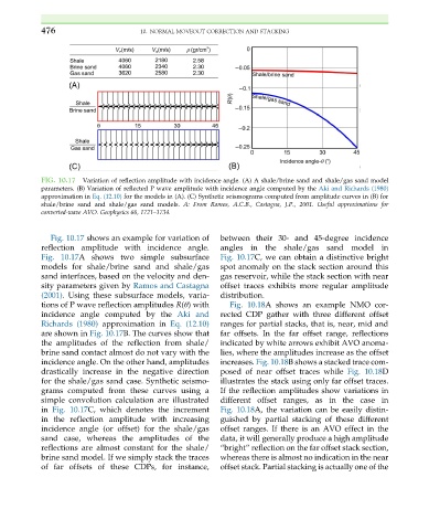
FIG. 10.17 Variation of reflection amplitude with incidence angle. (A) A shale/brine sand and shale/gas sand model
parameters. (B) Variation of reflected P wave amplitude with incidence angle computed by the Aki and Richards (1980)
approximation in Eq. (12.10) for the models in (A). (C) Synthetic seismograms computed from amplitude curves in (B) for
shale/brine sand and shale/gas sand models. A: From Ramos, A.C.B., Castagna, J.P., 2001. Useful approximations for
converted-wave AVO. Geophysics 66, 1721–1734.
Fig. 10.17 shows an example for variation of between their 30- and 45-degree incidence
reflection amplitude with incidence angle. angles in the shale/gas sand model in
Fig. 10.17A shows two simple subsurface Fig. 10.17C, we can obtain a distinctive bright
models for shale/brine sand and shale/gas spot anomaly on the stack section around this
sand interfaces, based on the velocity and den- gas reservoir, while the stack section with near
sity parameters given by Ramos and Castagna offset traces exhibits more regular amplitude
(2001). Using these subsurface models, varia- distribution.
tions of P wave reflection amplitudes R(θ) with Fig. 10.18A shows an example NMO cor-
incidence angle computed by the Aki and rected CDP gather with three different offset
Richards (1980) approximation in Eq. (12.10) ranges for partial stacks, that is, near, mid and
are shown in Fig. 10.17B. The curves show that far offsets. In the far offset range, reflections
the amplitudes of the reflection from shale/ indicated by white arrows exhibit AVO anoma-
brine sand contact almost do not vary with the lies, where the amplitudes increase as the offset
incidence angle. On the other hand, amplitudes increases. Fig. 10.18B shows a stacked trace com-
drastically increase in the negative direction posed of near offset traces while Fig. 10.18D
for the shale/gas sand case. Synthetic seismo- illustrates the stack using only far offset traces.
grams computed from these curves using a If the reflection amplitudes show variations in
simple convolution calculation are illustrated different offset ranges, as in the case in
in Fig. 10.17C, which denotes the increment Fig. 10.18A, the variation can be easily distin-
in the reflection amplitude with increasing guished by partial stacking of these different
incidence angle (or offset) for the shale/gas offset ranges. If there is an AVO effect in the
sand case, whereas the amplitudes of the data, it will generally produce a high amplitude
reflections are almost constant for the shale/ “bright” reflection on the far offset stack section,
brine sand model. If we simply stack the traces whereas there is almost no indication in the near
of far offsets of these CDPs, for instance, offset stack. Partial stacking is actually one of the