
Page 483 - Acquisition and Processing of Marine Seismic Data
P. 483
474 10. NORMAL MOVEOUT CORRECTION AND STACKING
data is collected as shot gathers in shot and improved proportional to √N because in-phase
receiver coordinates (Fig. 10.14A), and then primary reflection amplitudes strengthen each
transformed into shot and receiver midpoint other after stacking. Random noise components,
coordinates by CDP sorting (Fig. 10.14B), and however, are trace-by-trace inconsistent and are
the offset distance is removed by NMO correc- out-of-phase in the NMO corrected CDPs. After
tion to reduce all the traces into zero-offset summing up the traces during stacking, random
arrival times (Fig. 10.14C). Finally, the traces in noise is drastically suppressed, leading to an
the CDPs are summed up to produce a stacked improved S/N ratio. Fig. 10.16 shows an exam-
trace (Fig. 10.14D). ple to emphasize the effect of stacking on the
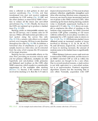
Stacking yields an interpretable seismic sec- random noise suppression. An NMO corrected
tion for 2D surveys, and a seismic cube for 3D synthetic CDP gather consisting of 120 traces
surveys. While a 2D stack section provides a ver- with two reflections of zero phase wavelets con-
tical section along the survey line only taminated by a 50% random noise is shown in
(Fig. 10.15A), a seismic cube allows us to extract Fig. 10.16A. Fig. 10.16B illustrates stacked traces
several, even irregular, 2D lines in any direction obtained using an increased number of traces
throughout the cube (Fig. 10.15B). In addition, a involved in stacking: 4, 12, 24, 36, 48, 60, 72,
horizontal slice of amplitudes at a given time 96, and 120 traces, respectively. As the number
sample, known as a time slice, can be extracted of traces in stacking increases, the amount of
from the cube, which exposes the 3D extension random noise in the stacked trace is significantly
of the target structure. reduced.
Stacking has two considerable effects on the Offset distance between source and receivers
data: First, providing an accurate velocity anal- is removed by NMO correction, and the traces in
ysis for primary reflections, multiples are still an NMO corrected CDP as well as within the
hyperbolic and out-of-phase while primaries stack section are thought to be a zero offset.
are flattened and in-phase on the CDPs after Due to several practical reasons, a stack section
NMO correction, which results in a considerable is not fully equivalent to a zero-offset section,
suppression of the multiples after stacking but is an approximation. Poststack migration
(Section 7.1). Second, if the number of traces algorithms assume that the incoming data is
involved in stacking is N, then the S/N ratio is zero offset. Normally, acquisition with CDP
FIG. 10.15 (A) An example stack section from a 2D survey, and (B) a seismic cube from a 3D survey.