
Page 486 - Acquisition and Processing of Marine Seismic Data
P. 486
10.4 SPECIFIC STACKING METHODS 477
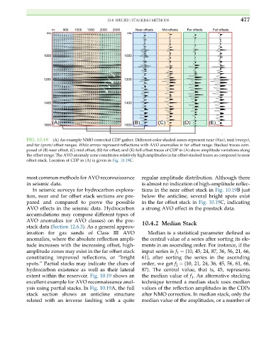
FIG. 10.18 (A) An example NMO corrected CDP gather. Different color shaded zones represent near (blue), mid (orange),
and far (green) offset ranges. White arrows represent reflections with AVO anomalies in far offset range. Stacked traces com-
posed of (B) near offset, (C) mid offset, (D) far offset, and (E) full offset traces of CDP in (A) show amplitude variations along
the offset range. The AVO anomaly zone constitutes relatively high amplitudes in far offset stacked traces as compared to near
offset stack. Location of CDP in (A) is given in Fig. 10.19C.
most common methods for AVO reconnaissance regular amplitude distribution. Although there
in seismic data. is almost no indication of high-amplitude reflec-
In seismic surveys for hydrocarbon explora- tions in the near offset stack in Fig. 10.19B just
tion, near and far offset stack sections are pre- below the anticline, several bright spots exist
pared and compared to prove the possible in the far offset stack in Fig. 10.19C, indicating
AVO effects in the seismic data. Hydrocarbon a strong AVO effect in the prestack data.
accumulations may compose different types of
AVO anomalies (or AVO classes) on the pre- 10.4.2 Median Stack
stack data (Section 12.6.3). As a general approx-
imation for gas sands of Class III AVO Median is a statistical parameter defined as
anomalies, where the absolute reflection ampli- the central value of a series after sorting its ele-
tude increases with the increasing offset, high- ments in an ascending order. For instance, if the
amplitude zones may exist in the far offset stack input series is f 1 ¼ {10, 45, 24, 87, 36, 56, 21, 66,
constituting improved reflections, or “bright 61}, after sorting the series in the ascending
spots.” Partial stacks may indicate the clues of order, we get f 2 ¼ {10, 21, 24, 36, 45, 56, 61, 66,
hydrocarbon existence as well as their lateral 87}. The central value, that is, 45, represents
extent within the reservoir. Fig. 10.19 shows an the median value of f 1 . An alternative stacking
excellent example for AVO reconnaissance anal- technique termed a median stack uses median
ysis using partial stacks. In Fig. 10.19A, the full values of the reflection amplitudes in the CDPs
stack section shows an anticline structure after NMO correction. In median stack, only the
related with an inverse faulting with a quite median value of the amplitudes, or a number of