
Page 154 - Advances in Renewable Energies and Power Technologies
P. 154
2. PV System Under Nonshading Conditions 127
The light-generated current is given as:
I LG ¼ I SCR G N þ I t ðT C T r Þ (4.10)
Cell temperature, T C , can be obtained from the following equation:
G
T C ¼ T a þ NOCT 25 C (4.11)
800
The diode current of the PV cell is similar to the standard diode:
h i
q
ðV PVC þR S I PVC Þ
I D ¼ I o e AKT c 1 (4.12)
The inverse saturation current of the pen junction can be expressed as:
3 qE G 1 1
T c AK T r T c
I o ¼ I or e (4.13)
T r
The current caused by the shunt resistance of the PV cell is
V PVC þ I PVC R S
¼ (4.14)
I R sh
R sh
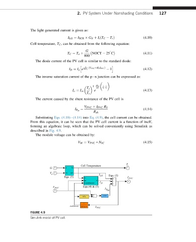
Substituting Eqs. (4.10)e(4.14) into Eq. (4.9), the cell current can be obtained.
From this equation, it can be seen that the PV cell current is a function of itself,
forming an algebraic loop, which can be solved conveniently using Simulink as
described in Fig. 4.9.
The module voltage can be obtained by:
V M ¼ V PVC N SC (4.15)
Cell Temperature c T
G 1 G Tc 1
a T 2 Ta Jph I
Equ. (3) Tc LG Equ. (1) I PVC
Vp Id 2
<Jcell(filtered)> I D
V PVC Equ (4) & (5) R I
3 SH
rs*u u/rsh
1
Jcell(filtered) 0.01s+1 I PVC
FIGURE 4.9
Simulink model of PV cell.