
Page 158 - Advances in Renewable Energies and Power Technologies
P. 158
2. PV System Under Nonshading Conditions 131
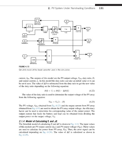
FIGURE 4.13
Simulink model of the boost converter used in the simulation.
current, I PV . The outputs of this model are the PVoutput voltage, V PV , duty ratio, D,
and output current, I o . In this model the duty ratio can take an initial value or it can
be set to zero. The value of DD is subtracted from the duty ratio to get the new value
of the duty ratio depending on the following equation:
Dðk þ 1Þ¼ DðkÞ DDðkÞ (4.22)
The value of the duty ratio is used to determine the output voltage of the PVarray
from the following equation:
V PV ¼ V o ð1 DÞ (4.23)
The PV voltage, V PV , obtained from Eq. (4.23) and the output current from PVarray
obtained from Eq. (4.9) are used to obtain the PVarray output voltage. An efficiency
factor can be used to determine the corresponding value of the output power. The
output current that feeds the battery and load can be obtained from dividing the
output power on the output voltage, V O .
2.1.4 Model of Calculating E and DE
The Simulink model of calculating E and DE is shown in Fig. 4.14. The input values
of this module are PVoutput current (I PV ) and PVoutput voltage (V PV ). These values
are used to calculate the power from PV array, P PV . Then, the error signal can be
calculated depending on Eq. (4.24). The value of DE is calculated as shown in
Eq. (4.25).