
Page 423 - Analog and Digital Filter Design
P. 423
420 Analog and Digital Filter Design
Input output
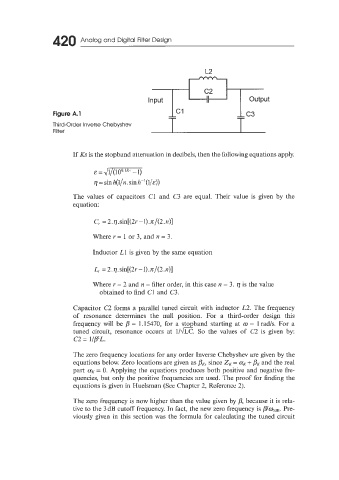
Figure A.l
Third-Order Inverse Chebyshev
Filter
If Ks is the stopband attenuation in decibels, then the following equations apply.
&=&qpKQ
q = sinh(l/rz.sinlz-'(l/&))
The values of capacitors C1 and C3 are equal. Their value is given by the
equation:
C,. = 2. q . sin[(2r - 1). n/(2. n)]
Where r = 1 or 3, and n = 3.
Inductor L1 is given by the same equation
L,- = 2. q. sin[(2r - 1).n/(2 A)]
Where I' = 2 and n = filter order, in this case n = 3. q is the value
obtained to find C1 and C3.
Capacitor C2 forms a parallel tuned circuit with inductor L2. The frequency
of resonance determines the null position. For a third-order design this
frequency will be p = 1.15470, for a stopband starting at w = 1 rad/s. For a
tuned circuit, resonance occurs at 1Im. So the values of C2 is given by:
c2 = l/P'L.
The zero frequency locations for any order Inverse Chebyshev are given by the
equations below. Zero locations are given as pK, since 2, = a, + pK and the real
part CC, = 0. Applying the equations produces both positive and negative fre-
quencies, but only the positive frequencies are used. The proof for finding the
equations is given in Huelsman (See Chapter 2, Reference 2).
The zero frequency is now higher than the value given by p, because it is rela-
tive to the 3 dB cutoff frequency. In fact, the new zero frequency is p/qde. Pre-
viously given in this section was the formula for calculating the tuned circuit