
Page 59 - Artificial Intelligence for Computational Modeling of the Heart
P. 59
Chapter 1 Multi-scale models of the heart for patient-specific simulations 29
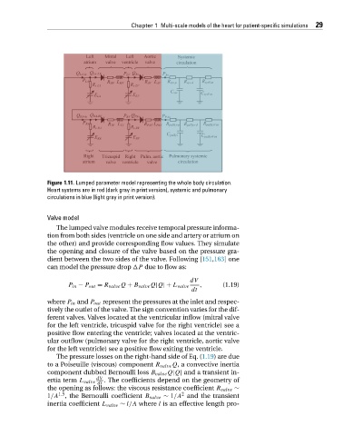
Figure 1.11. Lumped parameter model representing the whole body circulation.
Heart systems are in red (dark gray in print version), systemic and pulmonary
circulations in blue (light gray in print version).
Valve model
The lumped valve modules receive temporal pressure informa-
tion from both sides (ventricle on one side and artery or atrium on
the other) and provide corresponding flow values. They simulate
the opening and closure of the valve based on the pressure gra-
dient between the two sides of the valve. Following [151,163]one
can model the pressure drop
P due to flow as:
dV
P in − P out = R valve Q + B valve Q|Q|+ L valve , (1.19)
dt
where P in and P out represent the pressures at the inlet and respec-
tively the outlet of the valve. The sign convention varies for the dif-
ferent valves. Valves located at the ventricular inflow (mitral valve
for the left ventricle, tricuspid valve for the right ventricle) see a
positive flow entering the ventricle; valves located at the ventric-
ular outflow (pulmonary valve for the right ventricle, aortic valve
for the left ventricle) see a positive flow exiting the ventricle.
The pressure losses on the right-hand side of Eq. (1.19) are due
to a Poiseuille (viscous) component R valve Q, a convective inertia
component dubbed Bernoulli loss B valve Q|Q| and a transient in-
dV
ertia term L valve . The coefficients depend on the geometry of
dt
the opening as follows: the viscous resistance coefficient R valve ∼
2
1/A 1.5 , the Bernoulli coefficient B valve ∼ 1/A and the transient
inertia coefficient L valve ∼ l/A where l is an effective length pro-