
Page 458 - Automotive Engineering Powertrain Chassis System and Vehicle Body
P. 458
Decisional architecture C HAPTER 14.2
even in the absence of obstacles, planning the motion of (1990) considered thecasewherethecar canchange
a nonholonomic system is not straightforward. its direction of motion and extended Dubins’ results.
In the basic motion planning problem, the existence of This section first presents the model of the RS car.
a path between two configurations is characterized by the Then it summarizes its main properties and overviews
fact that these two configurations lie in the same the main path planning techniques that were
connected component of the collision-free configuration developed.
space of the robot. In other words, a holonomic robot can Model of the RS car Let A represent a RS car-like
2
reach any configuration within the connected component robot; it moves on a planar workspace W¼ R cluttered
of the configuration space where it is located. This up with a set of stationary obstacles B i ; i ˛f1; .; bg,
property no longer holds in the presence of nonholo- modelled as forbidden regions of W. A is modelled as
nomic constraints. Nonholonomy therefore raises a first a rigid body moving on the plane supported by four
problem which is: what is the reachable configuration wheels making point contact with the ground: two rear
space? The second problem is of course how to compute wheels and two directional front wheels. It is designed so
an admissible path, i.e. a path that respects the nonho- that the front wheels’ axles intersect the rear wheels’
lonomic constraints of the robot. axle at a given point C which is the rotation centre of A.
Nonholonomy appears in systems as different as It takes three parameters to characterize the position and
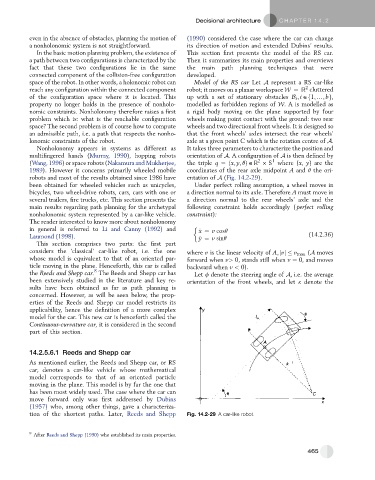
multifingered hands (Murray, 1990), hopping robots orientation of A. A configuration of A is then defined by
2
1
(Wang, 1996) or space robots (Nakamura and Mukherjee, the triple q ¼ðx; y; qÞ ˛R S where (x, y) are the
1989). However it concerns primarily wheeled mobile coordinates of the rear axle midpoint A and q the ori-
robots and most of the results obtained since 1986 have entation of A (Fig. 14.2-29).
been obtained for wheeled vehicles such as unicycles, Under perfect rolling assumption, a wheel moves in
bicycles, two wheel-drive robots, cars, cars with one or a direction normal to its axle. Therefore A must move in
several trailers, fire trucks, etc. This section presents the a direction normal to the rear wheels’ axle and the
main results regarding path planning for the archetypal following constraint holds accordingly ( perfect rolling
nonholonomic system represented by a car-like vehicle. constraint):
The reader interested to know more about nonholonomy
in general is referred to Li and Canny (1992) and _ x ¼ v cosq
Laumond (1998). _ y ¼ v sinq (14.2.36)
This section comprises two parts: the first part
considers the ‘classical’ car-like robot, i.e. the one where v is the linear velocity of A; jvj v max (A moves
whose model is equivalent to that of an oriented par- forward when v> 0, stands still when v ¼ 0, and moves
ticle moving in the plane. Henceforth, this car is called backward when v < 0).
8
the Reeds and Shepp car. The Reeds and Shepp car has Let f denote the steering angle of A, i.e. the average
been extensively studied in the literature and key re- orientation of the front wheels, and let k denote the
sults have been obtained as far as path planning is
concerned. However, as will be seen below, the prop-
erties of the Reeds and Shepp car model restricts its
applicability, hence the definition of a more complex
model for the car. This new car is henceforth called the
Continuous-curvature car, it is considered in the second
part of this section.
14.2.5.6.1 Reeds and Shepp car
As mentioned earlier, the Reeds and Shepp car, or RS
car, denotes a car-like vehicle whose mathematical
model corresponds to that of an oriented particle
moving in the plane. This model is by far the one that
has been most widely used. The case where the car can
move forward only was first addressed by Dubins
(1957) who, among other things, gave a characteriza-
tion of the shortest paths. Later, Reeds and Shepp Fig. 14.2-29 A car-like robot.
8
After Reeds and Shepp (1990) who established its main properties.
465