
Page 405 - 02. Subyek Computer Aided Design - Beginner’s Guide to SOLIDWORKS 2019- Level 1 by Alejandro Reyes
P. 405
Beginner's Guide to SOLIDWORKS 2019- Level I
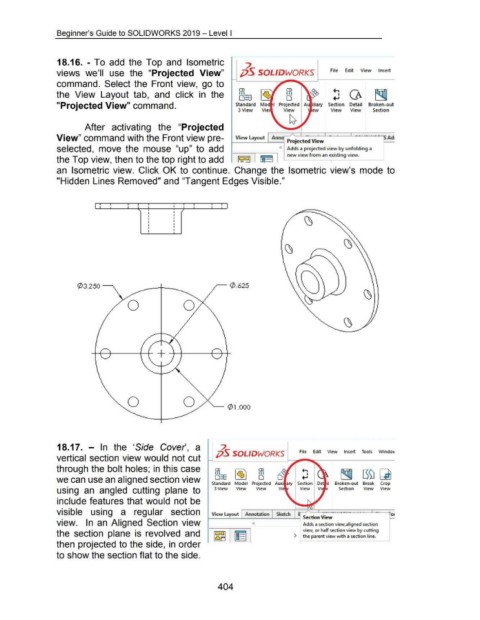
18.16. - To add the Top and Isometric
2
views we'll use the "Projected View" ;jS SOLIDWORKS File Edit View Insert
command. Select the Front view, go to
OJ OJ
the View Layout tab, and click in the Ill Ill ~ CA ~
o::s
0
"Projected View" command. Standard Mo I Projected Au iliary Section Detail Broken-out
3 View View ew View View Section
After activating the "Projected
View" command with the Front view pre- View layout Anno p 'ected-· v·. -- -- ~~SAd
rOJ 1ew
Selected, mOVe the mOUSe "up" tO add 0 Adds a projected view by unfolding a
the Top view, then to the top right to add ~~~] I~ II new viewfroman existing view.
an Isometric view. Click OK to continue. Change the Isometric view's mode to
"Hidden Lines Removed" and "Tangent Edges Visible."
I i : i : i I : : i : I
I
I
I
I
!
~3.250 -----,. ~ 0 .625
~ Q)l.OOO
18.17. - In the 'Side Cover', a 7.
pS SOLIDWORKS File Edit View Insert Tools Windov
vertical section view would not cut
through the bolt holes; in this case
~
CD ~ CD
o:a
Ill
Ill
we can use an aligned section view '1? D
Standard Model Projected Auxi ary Broken-out Break Crop
using an angled cutting plane to 3 View View View Vi Section View View
include features that would not be
visible using a regular section View Layout Annotation Sketch ~~
Adds a section view,aligned ·section J
___,--i Section View - ~
view. In an Aligned Section view 0
view, or half section view by cutting
the section plane is revolved and 1~ [~ 1 ) ~he parent view with a section line.
then projected to the side, in order
to show the section flat to the side.
404