
Page 52 - Biaxial Multiaxial Fatigue and Fracture
P. 52
Evaluation of Fatigue of Fillet Welded Joints in Vehicle Components Under Multiaxial Service Loads 31
Failure -cnl tical locations
/
::
- __ -->:- ~
complete submodel . * \ +* c Intersechon of weld root
c
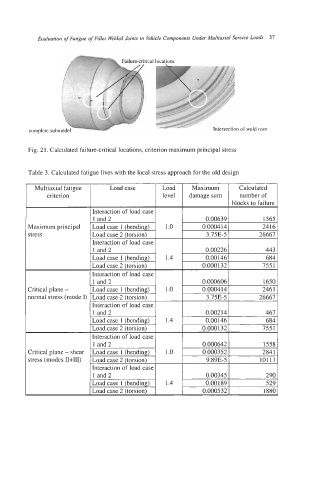
Fig. 21. Calculated failure-critical locations, criterion maximum principal stress
Table 3. Calculated fatigue lives with the local stress approach for the old design
Maximum Calculated
criterion level damage sum number of
blocks to failure
1 and 2 0.00639
Maximum principal 0.0004 I4
stress 3.75E-5 26667
0.00226
0.00 146
0.0001 32 755 1
Interaction of load case
1 and2 0.000606 1650
Critical plane - Load case 1 (bending) 1.0 0.0004 14 246 1
normal stress (mode I) Load case 2 (torsion) 3.75E-5 26667
Interaction of load case
1 and 2 0.00214 I 467
0.00146
0.000132
Interaction of load case
1 and2 0.000642
Critical plane - shear Load case 1 (bending) 1.0 0.000352
stress (modes n+m) Load case 2 (torsion) 9.89E-5 101 11
Interaction of load case
1 and 2 0.00345 290
Load case 1 (bending) 1.4 0.001 89 529
Load case 2 (torsion) 0.000532 1880