
Page 50 - Biaxial Multiaxial Fatigue and Fracture
P. 50
Evaluation of Fatigue of Fillet Welded Joints in Vehicle Components Under Multiaxial Service Loads 35
Fig. 16. Distribution of calculated damage - maximum principal stress criterion
FATIGUE LIFE CALCULATION FOR THE OLD DESIGN BASED ON THE LOCAL
STRESS APPROACH
Finite element modelling
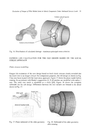
Fatigue life evaluation of the new design based on local elastic stresses clearly revealed that
the notch root is no longer critical. For comparison purposes, the old design as shown in Fig.
9 has also been treated with the local stress approach. Figure 17 shows the plane model before
rotating. In accordance with Radaj’s suggestions [2, 31 all notches are modelled with radius 1
mm. The weld root notch is modelled as a circle [20]. Figure 18 shows the complete
submodel for the old design. Differences between the two variants are limited to the detail
shown in Fig. 17.
detail>[ mes_hed-weld
Fig. 17. Plane submodel of the older geometry Fig. 18. Submodel of the older geometry
after rotating