
Page 49 - Biaxial Multiaxial Fatigue and Fracture
P. 49
34 G. SAYAIDIS ET AL.
situation exists at the fatigue-critical location. Unfortunately, it is very difficult to oversee the
situation without prior in-depth analysis.
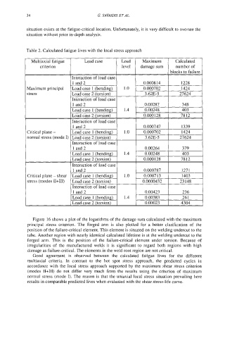
Table 2. Calculated fatigue lives with the local stress approach
Maximum principal
stress
Critical plane -
normal stress (mode I)
Critical plane - shear
stress (modes II+III)
Figure 16 shows a plot of the logarithms of the damage sum calculated with the maximum
principal stress criterion. The forged arm is also plotted for a better clarification of the
position of the failure-critical element. This element is situated on the welding undercut to the
tube. Another region with nearly identical calculated lifetime is at the welding undercut to the
forged arm. This is the position of the failure-critical element under torsion. Because of
irregularities of the manufactured welds it is significant to regard both regions with high
damage as failure-critical. The elements in the weld root region are not critical.
Good agreement is observed between the calculated fatigue lives for the different
multiaxial criteria. In contrast to the hot spot stress approach, the predicted cycles in
accordance with the local stress approach supported by the maximum shear stress criterion
(modes H+III) do not differ very much from the results using the criterion of maximum
normal stress (mode I). The reason is that the uniaxial local stress situation prevailing here
results in comparable predicted lives when evaluated with the shear stress-life curve.