
Page 200 - Biomedical Engineering and Design Handbook Volume 1, Fundamentals
P. 200
BIOMECHANICS OF THE MUSCULOSKELETAL SYSTEM 177
Muscle
CE
SEE
PEE
Tendon
Actuator
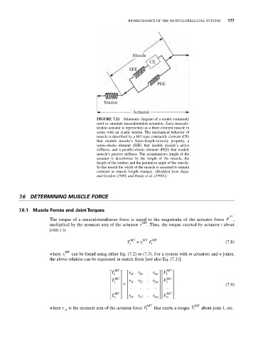
FIGURE 7.21 Schematic diagram of a model commonly
used to simulate musculotendon actuation. Each musculo-
tendon actuator is represented as a three-element muscle in
series with an elastic tendon. The mechanical behavior of
muscle is described by a Hill-type contractile element (CE)
that models muscle’s force-length-velocity property, a
series-elastic element (SEE) that models muscle’s active
stiffness, and a parallel-elastic element (PEE) that models
muscle’s passive stiffness. The instantaneous length of the
actuator is determined by the length of the muscle, the
length of the tendon, and the pennation angle of the muscle.
In this model the width of the muscle is assumed to remain
constant as muscle length changes. [Modified from Zajac
and Gordon (1989) and Pandy et al. (1990).]
7.6 DETERMINING MUSCLE FORCE
7.6.1 Muscle Forces and Joint Torques
MT
The torque of a musculotendinous force is equal to the magnitude of the actuator force F ,
multiplied by the moment arm of the actuator r MT . Thus, the torque exerted by actuator i about
joint j is
T j MT = r i MT F i MT (7.8)
MT
where r i can be found using either Eq. (7.2) or (7.3). For a system with m actuators and n joints,
the above relation can be expressed in matrix form [see also Eq. (7.1)]:
T ⎡ MT ⎤ r ⎡ r . r ⎤⎡ F MT ⎤
⎢ 1 ⎥ ⎢ 11 12 1 m ⎥⎢ 1 ⎥
T ⎢ 2 MT ⎥ r ⎢ 21 r 22 2 . r 2m ⎥⎢ F 2 MT ⎥
⎢ ⎥ = ⎢ ⎥⎢ ⎥ (7.9)
⎢ . ⎥ ⎢ . . . . ⎥⎢ . ⎥
⎢ MT ⎥ ⎢ ⎥⎢ MT ⎥
⎣ T n ⎦ ⎣ r 1 n r n 2 . r nm ⎦⎣ F F m ⎦
where r is the moment arm of the actuator force F 1 MT that exerts a torque T 1 MT about joint 1, etc.
11