
Page 356 - Biomedical Engineering and Design Handbook Volume 2, Applications
P. 356
334 DIAGNOSTIC EQUIPMENT DESIGN
time compared to most human activities, it is fairly long compared to distances covered by photons
traveling at the speed of light. Light travels approximately 30 cm/ns so that a 6 ns duration corre-
sponds to a distance uncertainty of about 90 cm, which is the approximate detector ring diameter. As
a result, the differential distance of the source between detectors has no observable effect on the tim-
ing of the coincidence events in conventional PET systems.
The arrival time of the annihilation photons is truly simultaneous only when the source is located
precisely midway between the two opposed coincidence detectors. If the source is displaced from the
midpoint, there will be a corresponding arrival time interval since one annihilation photon will have
a shorter distance to travel than the other. As discussed above, this time differential is too small to be
useful in conventionally designed PET systems. However, several of the scintillators used in PET
tomographs (e.g., LSO, LYSO) are capable of faster response than the 6 to 12 ns timing discussed
above. With appropriate electronics, the coincidence timing window has been reduced to 600 ps for
these detectors, yielding a source localization uncertainty of 9 cm. 24,25 Even with that reduction,
time-of-flight localization cannot be used to directly generate tomographic images, but it can be used
to regionally restrict the backprojection operation to areas where the sources are approximately
located. In current implementations, the inclusion of time-of-flight information reduces noise in the
reconstructed images by a factor of 2. Time-of-flight PET tomographs were actually commercially
available for a short time in the 1980s. These systems used BaF detectors which are very fast, but
2
unfortunately have very low detection efficiency. As a result, these devices did not compete well with
the conventional PET tomographs based on BGO. In 2006, a time-of-flight machine based on LYSO
detectors was reintroduced and is now commercially available. 26
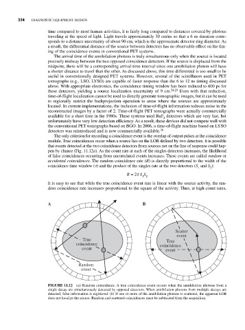
The only criterion for recording a coincidence event is the overlap of output pulses at the coincidence
module. True coincidences occur when a source lies on the LOR defined by two detectors. It is possible
that events detected at the two coincidence detectors from sources not on the line of response could hap-
pen by chance (Fig. 11.12a). As the count rate at each of the singles detectors increases, the likelihood
of false coincidences occurring from uncorrelated events increases. These events are called random or
accidental coincidences. The random coincidence rate (R) is directly proportional to the width of the
coincidence time window (t) and the product of the singles rate at the two detectors (S and S ):
1 2
R = 2t S S
1 2
It is easy to see that while the true coincidence event rate is linear with the source activity, the ran-
dom coincidence rate increases proportional to the square of the activity. Thus, at high count rates,
A B
Scatter
event
True True
coincidence coincidence
event event
Random
event
FIGURE 11.12 (a) Random coincidence. A true coincidence event occurs when the annihilation photons from a
single decay are simultaneously detected by opposed detectors. When annihilation photons from multiple decays are
detected, false information is registered. (b) If one or more of the annihilation photons is scattered, the apparent LOR
does not localize the source. Random and scattered coincidences must be subtracted from the acquisition.