
Page 358 - Biomedical Engineering and Design Handbook Volume 2, Applications
P. 358
336 DIAGNOSTIC EQUIPMENT DESIGN
A C
Detectors
3D
Sampling
Detectors
Detectors
B
Direct 2D Cross
planes Sampling planes
Detectors
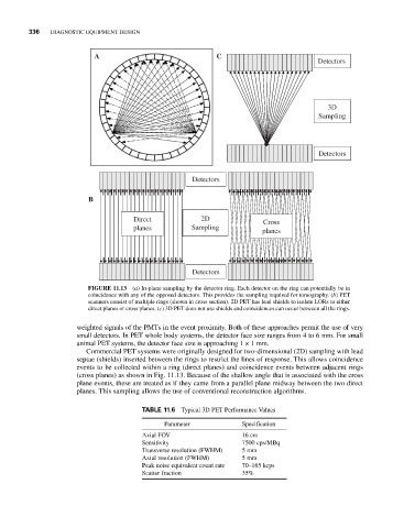
FIGURE 11.13 (a) In-plane sampling by the detector ring. Each detector on the ring can potentially be in
coincidence with any of the opposed detectors. This provides the sampling required for tomography. (b) PET
scanners consist of multiple rings (shown in cross section). 2D PET has lead shields to isolate LORs to either
direct planes or cross planes. (c) 3D PET does not use shields and coincidences can occur between all the rings.
weighted signals of the PMTs in the event proximity. Both of these approaches permit the use of very
small detectors. In PET whole body systems, the detector face size ranges from 4 to 6 mm. For small
animal PET systems, the detector face size is approaching 1 × 1 mm.
Commercial PET systems were originally designed for two-dimensional (2D) sampling with lead
septae (shields) inserted between the rings to restrict the lines of response. This allows coincidence
events to be collected within a ring (direct planes) and coincidence events between adjacent rings
(cross planes) as shown in Fig. 11.13. Because of the shallow angle that is associated with the cross
plane events, these are treated as if they came from a parallel plane midway between the two direct
planes. This sampling allows the use of conventional reconstruction algorithms.
TABLE 11.6 Typical 3D PET Performance Values
Parameter Specification
Axial FOV 16 cm
Sensitivity 7500 cps/MBq
Transverse resolution (FWHM) 5 mm
Axial resolution (FWHM) 5 mm
Peak noise equivalent count rate 70–165 kcps
Scatter fraction 35%