
Page 362 - Biomedical Engineering and Design Handbook Volume 2, Applications
P. 362
340 DIAGNOSTIC EQUIPMENT DESIGN
The annihilation photons traveling through the patient are attenuated largely through Compton
scatter interactions. The scattered photon resulting from this interaction loses energy and changes its
direction and the inclusion of the scattered event causes a loss of spatial resolution and image con-
trast. Scattered radiation is fairly easily handled in 2D PET studies because the scatter contribution
is about 10 to 15 percent of the acquired events. The scatter component is estimated by fitting the
recorded counts that extend beyond the patient boundary to a parabolic or Gaussian function in each
projection, which is subtracted from the projection. While this approach is not rigorous, it is suffi-
ciently accurate to correct for scatter in the 2D mode.
Because scatter is a major component of the detected counts in 3D PET, a more sophisticated
approach is required. Scatter is estimated from an algorithm that models the transport of photons
13
through the patient. The amount of scatter contaminating any given line of response depends on the
activity distribution as well as the tissue density in the patient. So, in order to compute the scatter
using this method, both the transmission data and the scatter-contaminated PET data have to be
reconstructed. The resultant images are used to estimate the amount of scatter that contributes to each
line of response. The scatter component is subtracted and the corrected projection data are presented
to the reconstruction algorithm. Although this approach appears to work well and has been adapted
on the commercial PET systems, there is still room for improvement. This approach only corrects
for activity within the field of view of the tomograph. In many cases, there is significant scatter that
originates outside the field of view. Also, the current approach assumes that the annihilation radia-
tion has only one scatter interaction. More sophisticated algorithms are being explored that will
expand the range of the correction to include the aforementioned cases. However, the ideal solution
is to have better energy resolution so that scatter can be eliminated during the acquisition.
Annihilation radiation like x-rays and gamma rays become less intense as they travel through
material objects. The loss of photons from the beam is referred to as attenuation. Attenuation is
exponential and as a result we can define a quantity called the half value layer (HVL). The half value
layer is the thickness of material that reduces the intensity of the radiation by half. For soft tissue
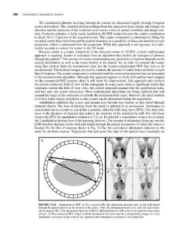
(water) the HVL for annihilation radiation is 7.2 cm. In order for a coincidence event to be recorded,
the 2 annihilation photons have to hit opposing detectors. The amount of attenuation along any specific
LOR therefore depends on the total path length through the patient irrespective of where the source is
located. For the line of response shown in Fig. 11.16a, the coincidence attenuation reduction is the
same for all three sources. Trajectories that just graze the edge of the patient have essentially no
A B
a
C
b
FIGURE 11.16 Attenuation in PET. (a) For a given LOR, the attenuation depends only on the path length
through the patient and not on the location of the source. Thus, the attenuation factor is the same for each source
shown along LOR a. The attenuation factor for LOR b is different than for LOR a, but is the same for each source
along b. (b) Reconstructed PET images without attenuation correction and the corresponding images (c), with
attenuation correction. Large artifacts are apparent when attenuation correction is not performed.