
Page 21 - Boiler plant and distribution system optimization manual
P. 21
6 Boiler Plant and Distribution System Optimization Manual
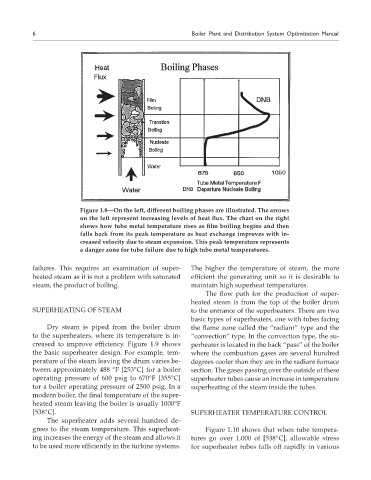
Figure 1.8—On the left, different boiling phases are illustrated. The arrows
on the left represent increasing levels of heat flux. The chart on the right
shows how tube metal temperature rises as film boiling begins and then
falls back from its peak temperature as heat exchange improves with in-
creased velocity due to steam expansion. This peak temperature represents
a danger zone for tube failure due to high tube metal temperatures.
failures. This requires an examination of super- The higher the temperature of steam, the more
heated steam as it is not a problem with saturated efficient the generating unit so it is desirable to
steam, the product of boiling. maintain high superheat temperatures.
The flow path for the production of super-
heated steam is from the top of the boiler drum
SUPERHEATING OF STEAM to the entrance of the superheaters. There are two
basic types of superheaters, one with tubes facing
Dry steam is piped from the boiler drum the flame zone called the “radiant” type and the
to the superheaters, where its temperature is in- “convection” type. In the convection type, the su-
creased to improve efficiency. Figure 1.9 shows perheater is located in the back “pass” of the boiler
the basic superheater design. For example, tem- where the combustion gases are several hundred
perature of the steam leaving the drum varies be- degrees cooler than they are in the radiant furnace
tween approximately 488 °F [253°C] for a boiler section. The gases passing over the outside of these
operating pressure of 600 psig to 670°F [355°C] superheater tubes cause an increase in temperature
tor a boiler operating pressure of 2500 psig. In a superheating of the steam inside the tubes.
modern boiler, the final temperature of the super-
heated steam leaving the boiler is usually 1000°F
[538°C]. SUPERHEATER TEMPERATURE CONTROL
The superheater adds several hundred de-
grees to the steam temperature. This superheat- Figure 1.10 shows that when tube tempera-
ing increases the energy of the steam and allows it tures go over 1,000 of [538°C], allowable stress
to be used more efficiently in the turbine systems. for superheater tubes falls off rapidly in various