
Page 124 - Cam Design Handbook
P. 124
THB5 8/15/03 1:52 PM Page 112
112 CAM DESIGN HANDBOOK
TABLE 5.1 Constraints for Example 1
Cam angle Displacement Velocity Acceleration
(degrees) (cm) (cm/rad) (cm/rad/rad)
0.00 0.00 0.00 0.00
36.0 0.05 — —
90.0 0.50 — 0.00
180.0 1.00 0.00 0.00
1
0
Displacement (cm)
Velocity (cm/rad)
Acceleration (cm/rad/rad)
Constraint
–1
0 45 90 135 180
Cam rotation angle (deg)
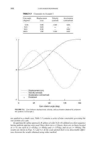
FIGURE 5.1. Cam follower displacement, velocity, and acceleration obtained by polynomi-
nal synthesis in Example 1.
are applied to a simple case. Table 5.1 contains a series of nine constraints governing the
rise portion of a cam.
In applying the spline approach, B-splines of order 6 (k = 6) defined on a knot sequence
having uniform spacing were used. Since there are n + k knots, there are six knots located
at x = 0, one each at x = 45deg, x = 90deg and x = 135deg, and six at x = 180deg. The
results are shown in Figs. 5.1 and 5.2. At the scale plotted there is no discernable differ-
ence between the results obtained using either method.