
Page 128 - Cam Design Handbook
P. 128
THB5 8/15/03 1:52 PM Page 116
116 CAM DESIGN HANDBOOK
1
0
Displacement (cm)
Velocity (cm/rad)
Acceleration (cm/rad/rad)
Constraint
–1
0 45 90 135 180
Cam rotation angle (deg.)
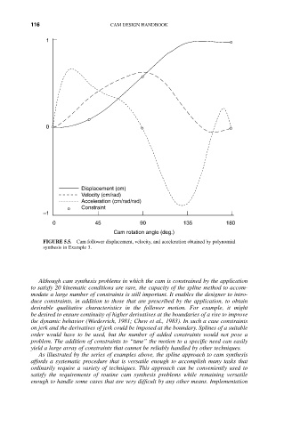
FIGURE 5.5. Cam follower displacement, velocity, and acceleration obtained by polynomial
synthesis in Example 3.
Although cam synthesis problems in which the cam is constrained by the application
to satisfy 20 kinematic conditions are rare, the capacity of the spline method to accom-
modate a large number of constraints is still important. It enables the designer to intro-
duce constraints, in addition to those that are prescribed by the application, to obtain
desirable qualitative characteristics in the follower motion. For example, it might
be desired to ensure continuity of higher derivatives at the boundaries of a rise to improve
the dynamic behavior (Wiederrich, 1981; Chew et al., 1983). In such a case constraints
on jerk and the derivatives of jerk could be imposed at the boundary. Splines of a suitable
order would have to be used, but the number of added constraints would not pose a
problem. The addition of constraints to “tune” the motion to a specific need can easily
yield a large array of constraints that cannot be reliably handled by other techniques.
As illustrated by the series of examples above, the spline approach to cam synthesis
affords a systematic procedure that is versatile enough to accomplish many tasks that
ordinarily require a variety of techniques. This approach can be conveniently used to
satisfy the requirements of routine cam synthesis problems while remaining versatile
enough to handle some cases that are very difficult by any other means. Implementation