
Page 125 - Cam Design Handbook
P. 125
THB5 8/15/03 1:52 PM Page 113
CAM MOTION SYNTHESIS USING SPLINE FUNCTIONS 113
1
0
Displacement (cm)
Velocity (cm/rad)
Acceleration (cm/rad/rad)
Constraint
–1
0 45 90 135 180
Cam rotation angle (deg.)
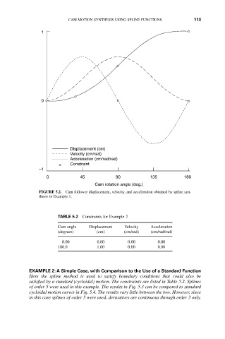
FIGURE 5.2. Cam follower displacement, velocity, and acceleration obtained by spline syn-
thesis in Example 1.
TABLE 5.2 Constraints for Example 2
Cam angle Displacement Velocity Acceleration
(degrees) (cm) (cm/rad) (cm/rad/rad)
0.00 0.00 0.00 0.00
180.0 1.00 0.00 0.00
EXAMPLE 2: A Simple Case, with Comparison to the Use of a Standard Function
Here the spline method is used to satisfy boundary conditions that could also be
satisfied by a standard (cycloidal) motion. The constraints are listed in Table 5.2. Splines
of order 5 were used in this example. The results in Fig. 5.3 can be compared to standard
cycloidal motion curves in Fig. 5.4. The results vary little between the two. However, since
in this case splines of order 5 were used, derivatives are continuous through order 3 only.