
Page 126 - Cam Design Handbook
P. 126
THB5 8/15/03 1:52 PM Page 114
114 CAM DESIGN HANDBOOK
1
0
Displacement (cm)
Velocity (cm/rad)
Acceleration (cm/rad/rad)
Constraint
–1
0 45 90 135 180
Cam rotation angle (deg.)
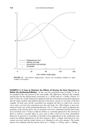
FIGURE 5.3. Cam follower displacement, velocity, and acceleration obtained by spline
synthesis in Example 2.
EXAMPLE 3: A Case to Illustrate the Effects of Varying the Knot Sequence to
Refine the Synthesized Motion In this case the constraints listed in Table 5.3 are to
be satisfied in the rise portion of the cam profile. The differences between this example
and the first are the displacement constraints at x = 36deg and at x = 90deg. Figures 5.5
and 5.6 show the results obtained by applying both the conventional polynomial approach
and the spline method with uniform spacing of the knots, exactly as was done in the first
example. In both cases all the constraints are satisfied, but there is a dip in the velocity
curve and a reversal of acceleration near the end of the rise. This feature is more pro-
nounced in the case of the polynomial function. Fig. 5.7 shows the result of adjusting the
positions of the interior knots: the acceleration reversal is eliminated and the peak value
of acceleration near 135deg is reduced. If there is a rational approach to the selection of
knots to achieve a specific effect in cases such as this, it has not yet been determined.
However, in general, it is possible to introduce local adjustments in the synthesized cam
motion by making adjustments in the knot sequence. Here, a simple trial-and-error pro-
cedure was used, and the results shown were obtained in only a few minutes. The results
shown were obtained with the interior knots at x = 50deg, x = 95deg, and x = 100deg.