
Page 146 - Cam Design Handbook
P. 146
THB5 8/15/03 1:52 PM Page 134
134 CAM DESIGN HANDBOOK
3
[w] : [T] 1 [w] : [T] 2
1
1
[w] : [T] 1 [w] : [T] 2
2
2
Velocity 1
–1
0 .5 1
Normalized time
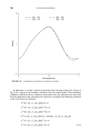
FIGURE 5.21. Comparison of cam-follower velocities in Example 7.
An alternative is to find a numerical procedure that will approximate the solution to
Eq. (5.22), subject to the boundary conditions from the output motion. These boundary
conditions result from the ten conditions listed earlier plus any additional ones that come
from the applications. By considering the original ten constraints, the following conditions
on the cam motion are obtained:
S ()+( K C (wb )) S 0 () = 0
1 ()
0
f
c
f
c
d
1 ( )
0
S c 2 () 0 ()+( K C (wb )) S () = 0
f
d
f
c
S ()+( K C (wb )) S c 2 ( ) 0 () = 0
3 ()
0
f
c
d
f
S ()+( K C (wb )) S 1 () = () ( K ) h C (wb )
1 ()
h K +
S 1
1
c f f d c s f c f d
2 () 1 ( )
1
S 1 ()+( K C (wb )) S () = 0
c f f d c
S ()+( K C (wb )) S c 2 ( ) 1 () = 0. (5.23)
3 ()
1
d
f
f
c