
Page 141 - Cam Design Handbook
P. 141
THB5 8/15/03 1:52 PM Page 129
CAM MOTION SYNTHESIS USING SPLINE FUNCTIONS 129
10
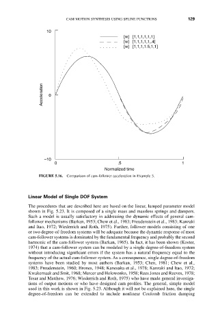
[w] [1,1,1,1,1,1]
[w] [1,1,1,1,1,.4]
[w] [1,1,1,1.5,1,1]
Acceleration 0
–10
0 .5 1
Normalized time
FIGURE 5.16. Comparison of cam-follower acceleration in Example 5.
Linear Model of Single DOF System
The procedures that are described here are based on the linear, lumped parameter model
shown in Fig. 5.23. It is composed of a single mass and massless springs and dampers.
Such a model is usually satisfactory in addressing the dynamic effects of general cam-
follower mechanisms (Barkan, 1953; Chew et al., 1983; Freudenstein et al., 1983; Kanzaki
and Itao, 1972; Wiederrich and Roth, 1975). Further, follower models consisting of one
or two degree-of-freedom systems will be adequate because the dynamic response of most
cam-follower systems is dominated by the fundamental frequency and probably the second
harmonic of the cam-follower system (Barkan, 1965). In fact, it has been shown (Koster,
1974) that a cam-follower system can be modeled by a single degree-of-freedom system
without introducing significant errors if the system has a natural frequency equal to the
frequency of the actual cam-follower system. As a consequence, single degree-of-freedom
systems have been studied by most authors (Barkan, 1953; Chen, 1981; Chew et al.,
1983; Freudenstein, 1960; Hrones, 1948; Kanesaka et al., 1978; Kanzaki and Itao, 1972;
Kwakernaak and Smit, 1968; Mercer and Holowenko, 1958; Rees Jones and Reeves, 1978;
Tesar and Matthew, 1976; Wiederrich and Roth, 1975) who have made general investiga-
tions of output motions or who have designed cam profiles. The general, simple model
used in this work is shown in Fig. 5.23. Although it will not be explained here, the single
degree-of-freedom can be extended to include nonlinear Coulomb friction damping