
Page 143 - Cam Design Handbook
P. 143
THB5 8/15/03 1:52 PM Page 131
CAM MOTION SYNTHESIS USING SPLINE FUNCTIONS 131
2
Velocity 1
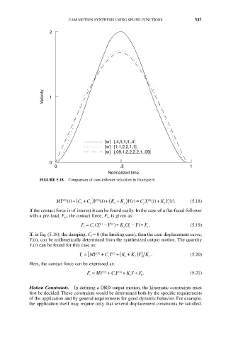
[w] [.4,1,1,1,.4]
[w] [1,1,2,2,1,1]
[w] [.09,1,2.2,2.2,1,.09]
0
0 .5 1
Normalized time
FIGURE 5.18. Comparison of cam-follower velocities in Example 6.
f )
C Y ()+(
MY ()+( C + ) 1 () t K + K Y t () = C Y ()+ K Y t (). (5.18)
2 ( )
1 ()
t
t
s f s fc fc
If the contact force is of interest it can be found easily. In the case of a flat-faced follower
with a pre-load, F p¢ , the contact force, F c , is given as:
(
(
() 1
F = C Y - Y )+ K Y - Y)+ F . (5.19)
() 1
f
c
c
p
f
c
If, in Eq. (5.18), the damping, C f = 0 (the limiting case), then the cam displacement curve,
Y c (t), can be arithmetically determined from the synthesized output motion. The quantity
Y c(t) can be found for this case as:
Y =[ MY () 2 + C Y +( K + K Y K . (5.20)
f ) ]
( ) 1
f
s
s
c
Here, the contact force can be expressed as:
F = MY () 2 + C Y + K Y + F . (5.21)
( ) 1
c s s p
Motion Constraints. In defining a DRD output motion, the kinematic constraints must
first be decided. These constraints would be determined both by the specific requirements
of the application and by general requirements for good dynamic behavior. For example,
the application itself may require only that several displacement constraints be satisfied.