
Page 145 - Cam Design Handbook
P. 145
THB5 8/15/03 1:52 PM Page 133
CAM MOTION SYNTHESIS USING SPLINE FUNCTIONS 133
1.2
[w] : [T] 1 [w] : [T] 2
1
1
[w] : [T] 1 [w] : [T] 2
2
2
Displacement .6
0
0 .5 1
Normalized time
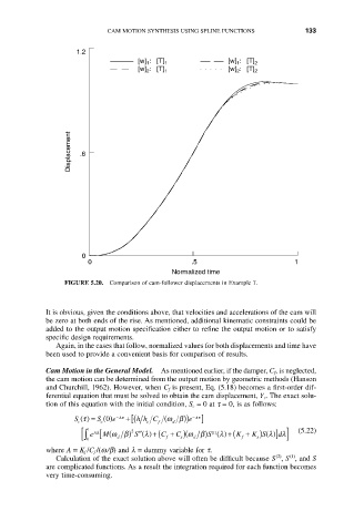
FIGURE 5.20. Comparison of cam-follower displacements in Example 7.
It is obvious, given the conditions above, that velocities and accelerations of the cam will
be zero at both ends of the rise. As mentioned, additional kinematic constraints could be
added to the output motion specification either to refine the output motion or to satisfy
specific design requirements.
Again, in the cases that follow, normalized values for both displacements and time have
been used to provide a convenient basis for comparison of results.
Cam Motion in the General Model. As mentioned earlier, if the damper, C f, is neglected,
the cam motion can be determined from the output motion by geometric methods (Hanson
and Churchill, 1962). However, when C f is present, Eq. (5.18) becomes a first-order dif-
ferential equation that must be solved to obtain the cam displacement, Y c. The exact solu-
tion of this equation with the initial condition, S c = 0at t = 0, is as follows:
-
At
S t () = S () 0 e - At + ( [ h h C ( w b)) e ]
c c c f d
1 2 K + ) ()] ] (5.22)
e [ M wb) ¢¢()+( C + )( S ()+( K S l dl
C wb)
(
S l
l
Al
() 1
[Ú 0 d f s d f s
where A = K f /C f /(w/b) and l = dummy variable for t.
(2)
(1)
Calculation of the exact solution above will often be difficult because S , S , and S
are complicated functions. As a result the integration required for each function becomes
very time-consuming.