
Page 140 - Cam Design Handbook
P. 140
THB5 8/15/03 1:52 PM Page 128
128 CAM DESIGN HANDBOOK
2
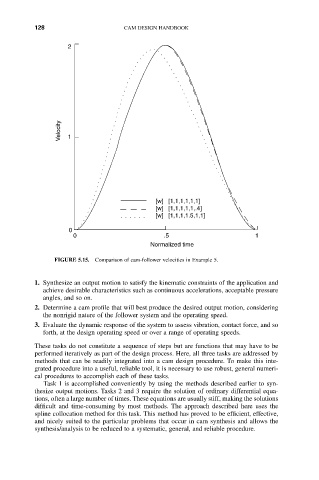
Velocity 1
[w] [1,1,1,1,1,1]
[w] [1,1,1,1,1,.4]
[w] [1,1,1,1.5,1,1]
0
0 .5 1
Normalized time
FIGURE 5.15. Comparison of cam-follower velocities in Example 5.
1. Synthesize an output motion to satisfy the kinematic constraints of the application and
achieve desirable characteristics such as continuous accelerations, acceptable pressure
angles, and so on.
2. Determine a cam profile that will best produce the desired output motion, considering
the nonrigid nature of the follower system and the operating speed.
3. Evaluate the dynamic response of the system to assess vibration, contact force, and so
forth, at the design operating speed or over a range of operating speeds.
These tasks do not constitute a sequence of steps but are functions that may have to be
performed iteratively as part of the design process. Here, all three tasks are addressed by
methods that can be readily integrated into a cam design procedure. To make this inte-
grated procedure into a useful, reliable tool, it is necessary to use robust, general numeri-
cal procedures to accomplish each of these tasks.
Task 1 is accomplished conveniently by using the methods described earlier to syn-
thesize output motions. Tasks 2 and 3 require the solution of ordinary differential equa-
tions, often a large number of times. These equations are usually stiff, making the solutions
difficult and time-consuming by most methods. The approach described here uses the
spline collocation method for this task. This method has proved to be efficient, effective,
and nicely suited to the particular problems that occur in cam synthesis and allows the
synthesis/analysis to be reduced to a systematic, general, and reliable procedure.