
Page 136 - Cam Design Handbook
P. 136
THB5 8/15/03 1:52 PM Page 124
124 CAM DESIGN HANDBOOK
1
R 1.5 R 6.5
R 2.5 R
5.5
.5
R 3.5 R 4.5
0
0 .5 1
Normalized time
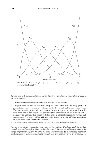
FIGURE 5.11. Rational B-splines (k = 5) constructed with the weight sequence of [1,
1, 1, 1, 1, 1] in Example 5.
the cam and follower contact forces during the rise. The following rationale was used in
pursuing this end:
1. The maximum acceleration values should be as low as possible.
2. The peak accelerations should occur early and late in the rise. The early peak will
prevent simultaneous occurrence of high inertia forces and high return spring forces.
The late negative peaks will occur when the return spring is compressed near its
maximum and is best capable of producing the acceleration of the follower that is
needed. The early and late peaks will also result in reduced magnitudes for the peak
acceleration. The overall effect will be a reduction in the spring stiffness needed and
an overall reduction in the contact forces.
3. The acceleration curves should remain smooth to avoid vibration problems.
The same six motion constraints and order of the rational B-splines used for the last
example are again applied. Also, the interior knot is fixed at the midpoint and only the
weight sequence is adjusted to refine the synthesized motions. By maintaining a symmet-
rical sequence of weights, symmetrical velocity and acceleration curves are preserved. As