
Page 137 - Cam Design Handbook
P. 137
THB5 8/15/03 1:52 PM Page 125
CAM MOTION SYNTHESIS USING SPLINE FUNCTIONS 125
1
R 1.5 R 6.5
R 5.5
R 2.5
.5 R
R 3.5 4.5
0
0 .5 1
Normalized time
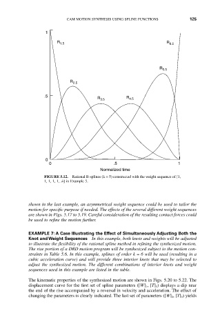
FIGURE 5.12. Rational B-splines (k = 5) constructed with the weight sequence of [1,
1, 1, 1, 1, .4] in Example 5.
shown in the last example, an asymmetrical weight sequence could be used to tailor the
motion for specific purpose if needed. The effects of the several different weight sequences
are shown in Figs. 5.17 to 5.19. Careful consideration of the resulting contact forces could
be used to refine the motion further.
EXAMPLE 7: A Case Illustrating the Effect of Simultaneously Adjusting Both the
Knot and Weight Sequences In this example, both knots and weights will be adjusted
to illustrate the flexibility of the rational spline method in refining the synthesized motion.
The rise portion of a DRD motion program will be synthesized subject to the motion con-
straints in Table 5.6. In this example, splines of order k = 6 will be used (resulting in a
cubic acceleration curve) and will provide three interior knots that may be selected to
adjust the synthesized motion. The different combinations of interior knots and weight
sequences used in this example are listed in the table.
The kinematic properties of the synthesized motion are shown in Figs. 5.20 to 5.22. The
displacement curve for the first set of spline parameters ([W] 1 , [T] 1 ) displays a dip near
the end of the rise accompanied by a reversal in velocity and acceleration. The effect of
changing the parameters is clearly indicated. The last set of parameters ([W] 2 , [T] 2 ) yields