
Page 142 - Cam Design Handbook
P. 142
THB5 8/15/03 1:52 PM Page 130
130 CAM DESIGN HANDBOOK
1
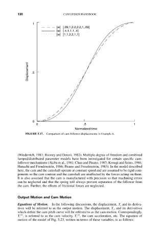
[w] [.09,1,2.2,2.2,1,.09]
[w] [.4,1,1,1,.4]
[w] [1,1,2,2,1,1]
Displacement .5
0
0 .5 1
Normalized time
FIGURE 5.17. Comparison of cam-follower displacements in Example 6.
(Wiederrich, 1981; Rooney and Deravi, 1982). Multiple degree-of-freedom and combined
lumped/distributed parameter models have been investigated for certain specific cam-
follower mechanisms (Akiba et al., 1981; Chan and Pisano, 1987; Kosugi and Seino, 1986;
Hanachi and Freudenstein, 1986; Pisano and Freudenstein, 1983). In the model described
here, the cam and the camshaft operate at constant speed and are assumed to be rigid com-
ponents so the cam contour and the camshaft are unaffected by the forces acting on them.
It is also assumed that the cam is manufactured with precision so that machining errors
can be neglected and that the spring will always prevent separation of the follower from
the cam. Further, the effects of frictional forces are neglected.
Output Motion and Cam Motion
Equations of Motion. In the following discussions, the displacement, Y, and its deriva-
tives will be referred to as the output motion. The displacement, Y c , and its derivatives
which define the cam pitch curve will be referred to as the cam motion. Correspondingly,
(2)
(1)
Y c , is referred to as the cam velocity, Y c , the cam acceleration, etc. The equation of
motion of the model of Fig. 5.23, written in terms of these variables, is as follows: