
Page 144 - Cam Design Handbook
P. 144
THB5 8/15/03 1:52 PM Page 132
132 CAM DESIGN HANDBOOK
10
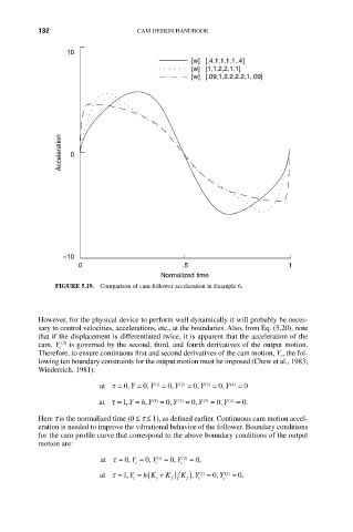
[w] [.4,1,1,1,1,.4]
[w] [1,1,2,2,1,1]
[w] [.09,1,2.2,2.2,1,.09]
Acceleration 0
–10
0 .5 1
Normalized time
FIGURE 5.19. Comparison of cam-follower acceleration in Example 6.
However, for the physical device to perform well dynamically it will probably be neces-
sary to control velocities, accelerations, etc., at the boundaries. Also, from Eq. (5.20), note
that if the displacement is differentiated twice, it is apparent that the acceleration of the
(2)
cam, Y c is governed by the second, third, and fourth derivatives of the output motion.
Therefore, to ensure continuous first and second derivatives of the cam motion, Y c, the fol-
lowing ten boundary constraints for the output motion must be imposed (Chew et al., 1983;
Wiederrich, 1981):
at t = 0, Y = 0, Y () 1 = 0, Y ( ) 2 = 0, Y ( ) 3 = 0, Y ( ) 4 = 0
h
at t =1, Y = , Y () 1 = 0, Y ( ) 2 = 0, Y ( ) 3 = 0, Y ( ) 4 = 0.
Here t is the normalized time (0 £ t £ 1), as defined earlier. Continuous cam motion accel-
eration is needed to improve the vibrational behavior of the follower. Boundary conditions
for the cam profile curve that correspond to the above boundary conditions of the output
motion are:
at t = 0, Y c = 0, Y c () 1 = 0, Y c ( ) 2 = 0,
at t =1, Y c = ( h K s + K f ) K f ), Y c () 1 = 0, Y c ( ) 2 = 0.