Page 550 - Cam Design Handbook
P. 550

THB16  9/19/03  8:04 PM  Page 538


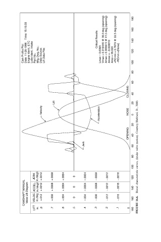
               Date: 11-26-1996    Time: 15:15:33    Critical Results Vmax = 0.019440 @ 36.0 deg (opening) Amax = 0.000974 @ 41.5 deg (opening)  +RCmin = 0.7679 @ 33.5 deg (opening)  180  160  140


              Cam Profile Plot  Engine Ident.: ETC  Lobe Ident.: Intake  Part No.:  Mfg. Dwg. No.:  Data Source:  Lift Data File:  Lmax = 0.6393  Anose = –0.000610  Area = 36.020   –RCmin =(None)  120  100


                                                                        80

                                                                        60
                                                                      CLOSING  40


                              Lift                                      20
                       Velocity                       Acceleration    NOSE  0


                                                                        20
                                                                      OPENING  40


                                              Jerk                      60 Diesel characteristic curves, (intake valve motion). Courtesy Hubbard, D., 2000.


                                                                        80

                                                                        100

                    JERK  in./deg3  +.0012  +.0008  +.0004  0  –.0004  –.0008  –.0012  –.0016  120
              CAMSHAFT MANUAL  Valve Lift Diagram  VELOC.  ACCEL.  in./deg  in./deg2  +.0012  +.012  +.0008  +.008  +.0004  +.004  0  0  –.0004  –.004  –.0008  –.008  –.0012  –.012  –.0016  –.016  140  160


                    LIFT  in.  .8  .7  .6  .5  .4    .3    .2   .1    0  180  FIGURE 16.6.
   545   546   547   548   549   550   551   552   553   554   555