
Page 549 - Cam Design Handbook
P. 549
THB16 9/19/03 8:04 PM Page 537
AUTOMOTIVE CAMSHAFT DYNAMICS 537
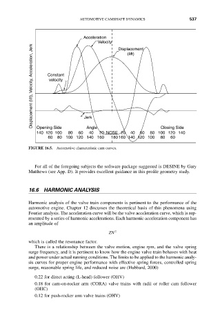
Acceleration
Velocity Displacement
Displacement (lift), Velocity, Acceleration, Jerk Constant
(lift)
velocity
Closing Side
Angle
Opening Side
40
140 120 100 80 60 Jerk 20 NOSE 20 40 60 80 100 120 140
60 80 100 120 140 160 180 160 140 120 100 80 60
FIGURE 16.5. Automotive characteristic cam curves.
For all of the foregoing subjects the software package suggested is DESINE by Gary
Matthews (see App. D). It provides excellent guidance in this profile geometry study.
16.6 HARMONIC ANALYSIS
Harmonic analysis of the valve train components is pertinent to the performance of the
automotive engine. Chapter 12 discusses the theoretical basis of this phenomena using
Fourier analysis. The acceleration curve will be the valve acceleration curve, which is rep-
resented by a series of harmonic accelerations. Each harmonic acceleration component has
an amplitude of
ZN 2
which is called the resonance factor.
There is a relationship between the valve motion, engine rpm, and the valve spring
surge frequency, and it is pertinent to know how the engine valve train behaves with heat
and power under actual running conditions. The limits to be applied to the harmonic analy-
sis curves for proper engine performance with effective spring forces, controlled spring
surge, reasonable spring life, and reduced noise are (Hubbard, 2000)
0.22 for direct acting (L-head) follower (OHV)
0.18 for cam-on-rocker arm (CORA) valve trains with radii or roller cam follower
(OHC)
0.12 for push-rocker arm valve trains (OHV)