
Page 134 - Complementarity and Variational Inequalities in Electronics
P. 134
A Variational Inequality Theory Chapter | 4 125
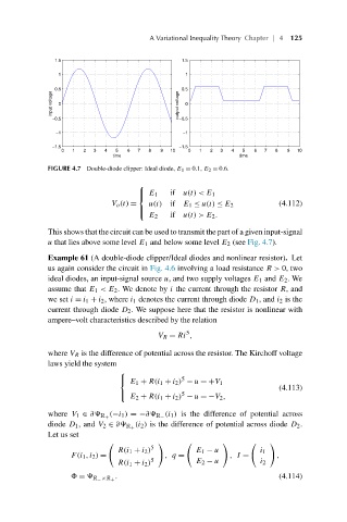
FIGURE 4.7 Double-diode clipper: Ideal diode, E 1 = 0.1, E 2 = 0.6.
⎧
⎪ E 1 if u(t) < E 1
⎨
V o (t) = u(t) if E 1 ≤ u(t) ≤ E 2 (4.112)
⎪
⎩ if u(t) > E 2 .
E 2
This shows that the circuit can be used to transmit the part of a given input-signal
u that lies above some level E 1 and below some level E 2 (see Fig. 4.7).
Example 61 (A double-diode clipper/Ideal diodes and nonlinear resistor). Let
us again consider the circuit in Fig. 4.6 involving a load resistance R> 0, two
ideal diodes, an input-signal source u, and two supply voltages E 1 and E 2 .We
assume that E 1 <E 2 . We denote by i the current through the resistor R, and
we set i = i 1 + i 2 , where i 1 denotes the current through diode D 1 , and i 2 is the
current through diode D 2 . We suppose here that the resistor is nonlinear with
ampere–volt characteristics described by the relation
5
V R = Ri ,
where V R is the difference of potential across the resistor. The Kirchoff voltage
laws yield the system
⎧
5
E 1 + R(i 1 + i 2 ) − u =+V 1
⎨
(4.113)
E 2 + R(i 1 + i 2 ) − u =−V 2 ,
⎩ 5
(i 1 ) is the difference of potential across
where V 1 ∈ ∂ R + (−i 1 ) =−∂ R −
(i 2 ) is the difference of potential across diode D 2 .
diode D 1 , and V 2 ∈ ∂ R +
Let us set
5
R(i 1 + i 2 ) E 1 − u i 1
F(i 1 ,i 2 ) = ,q = ,I = ,
R(i 1 + i 2 ) 5 E 2 − u i 2
. (4.114)
≡ R − ×R +