
Page 159 - Complete Wireless Design
P. 159
Amplifier Design
158 Chapter Three
rolloff of this circuit will then continue to flatten the gain as the undesired fre-
quencies decrease in value. However, the low frequencies may begin to display
an increasingly degraded return loss, so some empirical tweaking may be
required, both in software and on the lab bench, for optimized values of L, C,
and R.
3.3 Amplifier Biasing
3.3.1 Introduction
Classes of operation. Special classes of amplifier bias levels are utilized to
achieve different objectives, each with its own distinct advantages and disad-
vantages. The most prevalent classes of bias operation are Classes A, AB, B,
and C. All of these classes use circuit components to bias the transistor at a
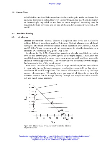
different DC operating, or Q, point (Fig. 3.56).
As shown in Fig. 3.57, Class A bias permits a signal’s amplified current to
flow for the entire cycle, or 360 degrees, of the input signal. This allows the
amplified output signal to never reach saturation or cutoff, and thus stay with-
in linear operating parameters. The output will be a relatively accurate ampli-
fied representation of the input signal.
Because of their low efficiency, Class A single-ended amplifiers are ordinar-
ily used only in small-signal, nonpower applications, especially as low-distor-
tion linear RF and IF amplifiers. This lack of efficiency is caused by the large
amount of continuous DC supply power required at all times to produce the
constant current that is always flowing through the amplifier—with or with-
out any input signal present.
Figure 3.56 The locations of various bias Q points for different
amplifier classes.
Downloaded from Digital Engineering Library @ McGraw-Hill (www.digitalengineeringlibrary.com)
Copyright © 2004 The McGraw-Hill Companies. All rights reserved.
Any use is subject to the Terms of Use as given at the website.